Electronic Warfare and Radar Systems Engineering Handbook |
|
|
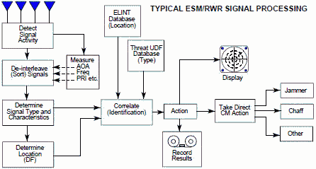
SIGNAL SORTING METHODS and DIRECTION FINDING As shown in Figure 1, signal processing is basically a problem of signal detection, emitter parameter measurement and correlation, emitter sorting, identification, and operator notification. The ultimate goal of this processing is to classify radar signals by their unique characteristics and to use this data to identify enemy radars operating in the environment, determine their location or direction, assess their threat to friendly forces, and display this information to the operator.
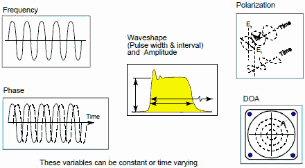
Figure 1. Signal Processing Steps While not all electronic support measures (ESM) or radar warning receiver (RWR) systems perform every step in this process, each completes some of them. For example, ESM systems seldom initiate direct CM action, while RWRs sometimes do. Also ESM systems frequently record electronic data for future use, but few RWRs do. ESM systems place more emphasis on accurate emitter location and hence direction finding capabilities, while RWRs usually give a rough estimate of position/distance. The typical emitter characteristics that an ESM system can measure for a pulse radar include the following data: 1. Radio Frequency (RF) 2. Amplitude (power) 3. Direction of Arrival (DOA) - also called Angle of Arrival (AOA) 4. Time of Arrival (TOA) 5. Pulse Repetition Interval (PRI) 6. PRI type 7. Pulse Width (PW) 8. Scan type and rate 9. Lobe duration (beam width) However, this list is not comprehensive. Other emitter parameters are available which may be necessary to characterize the threat system. More sophisticated ESM systems can measure additional parameters, such as PRI modulation characteristics, inter-and intra-pulse Frequency Modulation (FM), missile guidance characteristics (e.g., pattern of pulse spacing within a pulse group), and Continuous Wave (CW) signals. Still other parameters which can describe an electromagnetic wave but are currently not commonly used for identification include polarization and phase. However, as threat emitters begin to use this data more frequently to avoid jamming the more important they may become in identifying signals. Some of the emitter characteristics which describe an electromagnetic wave are shown in Figure 2.
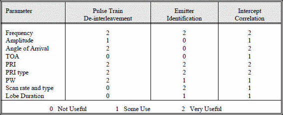
Figure 2. Information Content of an Electromagnetic Wave Table 1 illustrates the relative importance of several measured parameters during various stages of signal processing.
Table 1. Importance of Emitter Parameters During Signal Processing
Some emitter parameters can be measured using a single pulse; these parameters are referred to as monopulse parameters. The monopulse parameters include RF, PW, DOA, amplitude and TOA. RF can be determined on a pulse-by-pulse basis by receivers that can measure frequency. Frequency is very useful for emitter identification since most radars operate at a single frequency. Most real-time systems measure pulse width instead of pulse shape because the latter is much more difficult to characterize mathematically. Unfortunately, the apparent pulse width can be severely distorted by reflections, and consequently, its usefulness for emitter identification is limited. DOA cannot be used for emitter identification, but is excellent for sorting signals. A number of ESM systems use both frequency and DOA information to distinguish the new signals from the old (that is, known) ones. Amplitude also cannot be used for emitter identification. However, it can be used for sorting and for gross distance estimation using precompiled emitter's effective radiated power. Moreover, amplitude in conjunction with TOA can be used to determine the emitter's scan characteristics./p> Other emitter parameters such as PRI, guidance and scan characteristics can be determined only by analyzing a group of pulses. All these parameters are useful for emitter identification; unfortunately, they require time for data collection and analysis, and call for sophisticated signal processing algorithms. The problem of signal recognition in real-time is complicated by two factors: modulation of the signals and the very high pulse densities expected in the environment. Complex modulations (for example, inter-pulse RF modulation, intra-pulse RF modulation and agile Pulse Repetition Frequencies (PRFs)) present a significant pattern recognition problem for a number of ESM systems. It is expected that during some missions, hundreds of emitters will be transmitting simultaneously in the same vicinity. Wide-open antenna/receiver combination systems may have to cope with up to a million PPS. Even narrow-band receivers can expect data rates up to 100,000 PPS. At these rates, a single modern computer cannot be expected to process all the pulses, derive the characteristics for all emitters and identify the emitters in real-time. Other factors which encumber signal recognition include missing pulses, atmospheric noise and multiple reflections of pulses. Present RWRs are designed primarily to cope with stable emitters. A stable emitter is one whose frequency and pulse repetition interval (PRI) remain relatively constant from pulse to pulse. The future threat will move steadily away from the stable emitter towards agile emitters which vary their frequency and PRI characteristics. The first change in this direction is towards the patterned agile emitter which varies its pulse and frequency parameters in accordance with a specific pattern. Examples of patterned agile emitters are MTI radars which use staggered PRFs, pulse Doppler radars which change frequency and PRF on a block-to-block basis, and certain frequency-agile radars whose transmitter frequency is mechanically modulated in a systematic pattern (e.g., spin-tuned magnetron). The next step in this evolution is towards truly agile emitters which change their frequency and PRF in a random manner on a pulse-to-pulse basis. One tempering factor in this evolution is that radars which process Doppler must maintain a constant frequency for at least two consecutive pulses. In addition to agile frequency and PRI parameters, the future threat will be composed of a number of high-PRF pulsed Doppler, burst-frequency, CW, pulse-compression, agile-beam, and LPI radars, which use pseudo-noise waveforms. This conglomeration of radar types will cause a high signal density which must be segmented into a manageable data stream by the use of both frequency and spatial filtering in the RWR. While frequency and PRI are good parameters for sorting present-day non-agile emitters, they are poor or useless parameters for sorting agile emitters.
Table of Contents for Electronics Warfare and Radar Engineering Handbook Introduction | Abbreviations | Decibel | Duty Cycle | Doppler Shift | Radar Horizon / Line of Sight | Propagation Time / Resolution | Modulation | Transforms / Wavelets | Antenna Introduction / Basics | Polarization | Radiation Patterns | Frequency / Phase Effects of Antennas | Antenna Near Field | Radiation Hazards | Power Density | One-Way Radar Equation / RF Propagation | Two-Way Radar Equation (Monostatic) | Alternate Two-Way Radar Equation | Two-Way Radar Equation (Bistatic) | Jamming to Signal (J/S) Ratio - Constant Power [Saturated] Jamming | Support Jamming | Radar Cross Section (RCS) | Emission Control (EMCON) | RF Atmospheric Absorption / Ducting | Receiver Sensitivity / Noise | Receiver Types and Characteristics | General Radar Display Types | IFF - Identification - Friend or Foe | Receiver Tests | Signal Sorting Methods and Direction Finding | Voltage Standing Wave Ratio (VSWR) / Reflection Coefficient / Return Loss / Mismatch Loss | Microwave Coaxial Connectors | Power Dividers/Combiner and Directional Couplers | Attenuators / Filters / DC Blocks | Terminations / Dummy Loads | Circulators and Diplexers | Mixers and Frequency Discriminators | Detectors | Microwave Measurements | Microwave Waveguides and Coaxial Cable | Electro-Optics | Laser Safety | Mach Number and Airspeed vs. Altitude Mach Number | EMP/ Aircraft Dimensions | Data Busses | RS-232 Interface | RS-422 Balanced Voltage Interface | RS-485 Interface | IEEE-488 Interface Bus (HP-IB/GP-IB) | MIL-STD-1553 & 1773 Data Bus | This HTML version may be printed but not reproduced on websites. |
|


