Electronic Warfare and Radar Systems Engineering Handbook |
|||||||||||||||||||||||||||||||||||||||||||||||||||||||||||||||||||||||||||||||||||||||||||||||||||||||||||||||||||||||||||
|
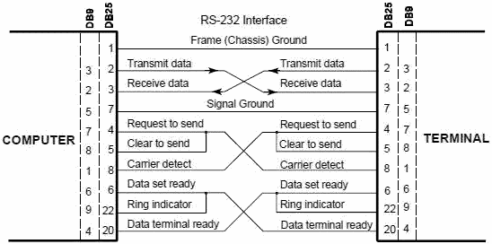
RS-232 INTERFACE Introduction: The RS-232 interface is the Electronic Industries Association (EIA) standard for the interchange of serial binary data between two devices. It was initially developed by the EIA to standardize the connection of computers with telephone line modems. The standard allows as many as 20 signals to be defined, but gives complete freedom to the user. Three wires are sufficient: send data, receive data, and signal ground. The remaining lines can be hardwired on or off permanently. The signal transmission is bipolar, requiring two voltages, from 5 to 25 volts, of opposite polarity. Communication Standards: The industry custom is to use an asynchronous word consisting of: a start bit, seven or eight data bits, an optional parity bit and one or two stop bits. The baud rate at which the word sent is device-dependent. The baud rate is usually 150 times an integer power of 2, ranging from 0 to 7 (150, 300, 600 ,...., 19,200 ). Below 150 baud, many system-unique rates are used. The standard RS-232-C connector has 25 pins, 21 pins which are used in the complete standard. Many of the modem signals are not needed when a computer terminal is connected directly to a computer, and Figure 1 illustrates how some of the "spare" pins should be linked if not needed. Figure 1 also illustrates the pin numbering used in the original DB-25 connector and that now commonly used with a DB-9 connector normally used in modern computers Specifying compliance to RS-232 only establishes that the signal levels in two devices will be compatible and that if both devices use the suggested connector, they may be able to be connected. Compliance to RS-232 does not imply that the devices will be able to communicate or even acknowledge each other's presence.
Figure 1. Direct-to-computer RS-232 Interface Table 1 shows the signal names, and functions of the RS-232 serial port pinout. Table 2 shows a complete pin description.
Table 1. RS-232 Serial Port Pinout
Table 2. RS-232C Interface Signals.
Electrical Characteristics: The RS-232-C specifies the signaling rate between the DTE and DCE, and a digital signal is used on all interchange circuits. The RS-232 standard specifies that logic "1" is to be sent as a voltage in the range -15 to -5 V and that logic "0" is to sent as a voltage in the range +5 to +15 V. The standard specifies that voltages of at least 3 V in amplitude will always be recognized correctly at the receiver according to their polarity, so that appreciable attenuation along the line can be tolerated. The transfer rate is rated > 20 kbps and a distance of < 15m. Greater distance and data rates are possible with good design, but it is reasonable to assume that these limits apply in practice as well as in theory. The load impedance of the terminator side of the interface must be between 3000 and 7000 ohms, and not more than 2500pF. Table 3, summarizes the functional specifications of the most important circuits.
Table 3. RS-232-C Circuit Definitions
Range: The RS-232-C standard specifies that the maximum length of cable between the transmitter and receiver should not exceed 100 feet, Although in practice many systems are used in which the distance between transmitter and receiver exceeds this rather low figure. The limited range of the RS-232C standard is one of its major shortcomings compared with other standards which offer greater ranges within their specifications. One reason why the range of the RS-232C standard is limited is the need to charge and discharge the capacitance of the cable connecting the transmitter and receiver. Mechanical Characteristics: The connector for the RS-232-C is a 25 pin connector with a specific arrangement of wires. In theory, a 25 wire cable could be used to connect the Data Terminal Equipment (DTE) to the Data Communication Equipment (DCE). The DTE is a device that is acting as a data source , data sink, or both, e.g. a terminal, peripheral or computer. The DCE is a device that provides the functions required to establish, maintain, and terminate a data-transmission connecting, as well as the signal conversion, and coding required for communication between data terminal equipment and data circuit; e.g. a modem. Table 4, shows the complete summary of the RS-232-C, e.g., descriptor, sponsor, data format, etc.
Table of Contents for Electronics Warfare and Radar Engineering Handbook Introduction | Abbreviations | Decibel | Duty Cycle | Doppler Shift | Radar Horizon / Line of Sight | Propagation Time / Resolution | Modulation | Transforms / Wavelets | Antenna Introduction / Basics | Polarization | Radiation Patterns | Frequency / Phase Effects of Antennas | Antenna Near Field | Radiation Hazards | Power Density | One-Way Radar Equation / RF Propagation | Two-Way Radar Equation (Monostatic) | Alternate Two-Way Radar Equation | Two-Way Radar Equation (Bistatic) | Jamming to Signal (J/S) Ratio - Constant Power [Saturated] Jamming | Support Jamming | Radar Cross Section (RCS) | Emission Control (EMCON) | RF Atmospheric Absorption / Ducting | Receiver Sensitivity / Noise | Receiver Types and Characteristics | General Radar Display Types | IFF - Identification - Friend or Foe | Receiver Tests | Signal Sorting Methods and Direction Finding | Voltage Standing Wave Ratio (VSWR) / Reflection Coefficient / Return Loss / Mismatch Loss | Microwave Coaxial Connectors | Power Dividers/Combiner and Directional Couplers | Attenuators / Filters / DC Blocks | Terminations / Dummy Loads | Circulators and Diplexers | Mixers and Frequency Discriminators | Detectors | Microwave Measurements | Microwave Waveguides and Coaxial Cable | Electro-Optics | Laser Safety | Mach Number and Airspeed vs. Altitude Mach Number | EMP/ Aircraft Dimensions | Data Busses | RS-232 Interface | RS-422 Balanced Voltage Interface | RS-485 Interface | IEEE-488 Interface Bus (HP-IB/GP-IB) | MIL-STD-1553 & 1773 Data Bus | This HTML version may be printed but not reproduced on websites. |
|||||||||||||||||||||||||||||||||||||||||||||||||||||||||||||||||||||||||||||||||||||||||||||||||||||||||||||||||||||||||||