Electronic Warfare and Radar Systems Engineering Handbook |
|
MACH NUMBER and AIRSPEED vs. ALTITUDE MACH NUMBER MACH NUMBER is defined as a speed ratio, referenced to the speed of sound, i.e.
MACH NUMBER = (at the given atmospheric conditions)
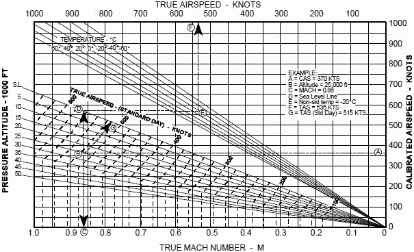
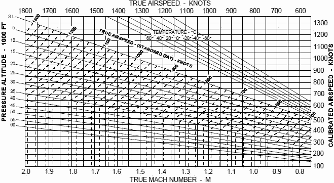
Since the temperature and density of air decreases with altitude, so does the speed of sound, hence a given true velocity results in a higher MACH number at higher altitudes. AIRSPEED is a term that can be easily confused. The unqualified term airspeed can mean any of the following: a. Indicated airspeed (IAS) - the airspeed shown by an airspeed indicator in an aircraft. Indicated airspeed is expressed in knots and is abbreviated KIAS. b. Calibrated airspeed (CAS) - indicated airspeed corrected for static source error due to location of pickup sensor on aircraft. Calibrated airspeed is expressed in knots and is abbreviated KCAS. Normally it doesn't differ much from IAS. c. True airspeed (TAS) - IAS corrected for instrument installation error, compressibility error, and errors due to variations from standard air density. TAS is expressed in knots and is abbreviated KTAS. TAS is approximately equal to CAS at sea level but increases relative to CAS as altitude increases. At 35,000 ft, 250 KIAS (or KCAS) is approximately 430 KTAS. IAS (or CAS) is important in that aircraft dynamics (such as stall speed) responds largely to this quantity. TAS is important for use in navigation (True airspeed ± windspeed = groundspeed). Figures 1 and 2 depict relations between CAS and TAS for various altitudes and non-standard temperature conditions. The first graph depicts lower speed conditions, the second depicts higher speeds. As an example of use, consider the chart on the next page. Assume we are in the cockpit, have read our IAS from the airspeed indicator, and have applied the aircraft specific airspeed correction to obtain 370 KCAS. We start at point "A" and go horizontally to our flight altitude at point "B" (25,000 ft in this case). To find our Mach, we go down vertically to point "C" to obtain 0.86 Mach. To get our TAS at our actual environmental conditions, we go from point "B" vertically until we hit the Sea Level (S.L.) reference line at point "D", then travel horizontally until we reach our actual outside air temperature (-20°C at altitude) at point "E", then go up vertically to read our actual TAS from the scale at point "F" (535 KTAS). If we wanted our TAS at "standard" temperature and pressure conditions, we would follow the dashed lines slanting upward from point "B" to point "G" and read 515 KTAS from the scale. Naturally, we could go into the graph at any point and go "backwards" to find CAS from true Mach or TAS.
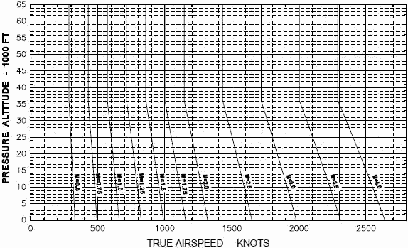
Figure 3 shows a much wider range of Mach numbers. It contains only TAS and Mach, since aircraft generally do not fly above Mach 2, but missiles (which don't have airspeed indicators) do. The data on this graph can be obtained directly from the following formula for use at altitudes of 36,000 ft and below:
The speed of sound calculated from this formula can be used with the equation on the first page to obtain Mach number. This equation uses the standard sea level temperature of 59E F and a lapse rate of -3.57°/1000 ft altitude. Temperature stabilizes at -69.7° F at 36,000 ft so the speed of sound stabilizes there at 573 knots. See the last page of this section for a derivation of equation [2].
Figure 1. TAS and CAS Relationship with Varying Altitude and Temperature
Figure 2. TAS and CAS Relationship with Varying Altitude and Temperature (Continued)
Figure 3. Mach Number vs TAS Variation with Altitude The following is a derivation of equation [2] for the speed of sound: Given: p = pressure (lb/ft2) T = absolute temperature (°Rankine) = °F + 459.7 v = specific volume (ft3/lb) w = specific weight (lb/ft3) = 1/ν R = a constant (for air: R = 53.3) ρ = density = w/g = 1/gν ? ν = 1/gρ From Boyle's law of gasses: pν = RT , therefore we have: p/ρ = gRT = (32.2)(53.3)T = 1718 T [3] It can also be shown that: p/ργ = constant; for air γ = 1.4 [4] From the continuity equation applied to a sound wave: ρAVa = (ρ+dρ)A(Va + dVa) [5] Expanding and dropping insignificant terms gives: dVa = -Va dρ/ρ [6] Using Newton's second law (p + ρVa/2 = a constant) and taking derivatives: dp = -ρVadVa substituting into [6] gives: Va2 = dp/dρ [7] 2 Then taking derivatives of [4] and substituting in [7] gives:
Then using [3] gives: Using a "Standard" atmosphere of 59° F @ Sea Level (S.L.) and a lapse rate of -3.57°/1000 ft altitude:
Table of Contents for Electronics Warfare and Radar Engineering Handbook Introduction | Abbreviations | Decibel | Duty Cycle | Doppler Shift | Radar Horizon / Line of Sight | Propagation Time / Resolution | Modulation | Transforms / Wavelets | Antenna Introduction / Basics | Polarization | Radiation Patterns | Frequency / Phase Effects of Antennas | Antenna Near Field | Radiation Hazards | Power Density | One-Way Radar Equation / RF Propagation | Two-Way Radar Equation (Monostatic) | Alternate Two-Way Radar Equation | Two-Way Radar Equation (Bistatic) | Jamming to Signal (J/S) Ratio - Constant Power [Saturated] Jamming | Support Jamming | Radar Cross Section (RCS) | Emission Control (EMCON) | RF Atmospheric Absorption / Ducting | Receiver Sensitivity / Noise | Receiver Types and Characteristics | General Radar Display Types | IFF - Identification - Friend or Foe | Receiver Tests | Signal Sorting Methods and Direction Finding | Voltage Standing Wave Ratio (VSWR) / Reflection Coefficient / Return Loss / Mismatch Loss | Microwave Coaxial Connectors | Power Dividers/Combiner and Directional Couplers | Attenuators / Filters / DC Blocks | Terminations / Dummy Loads | Circulators and Diplexers | Mixers and Frequency Discriminators | Detectors | Microwave Measurements | Microwave Waveguides and Coaxial Cable | Electro-Optics | Laser Safety | Mach Number and Airspeed vs. Altitude Mach Number | EMP/ Aircraft Dimensions | Data Busses | RS-232 Interface | RS-422 Balanced Voltage Interface | RS-485 Interface | IEEE-488 Interface Bus (HP-IB/GP-IB) | MIL-STD-1553 & 1773 Data Bus | This HTML version may be printed but not reproduced on websites. |
 [1]
[1] [2]
[2]


 [8]
[8] [9]
[9] which is equation [2]