Electronic Warfare and Radar Systems Engineering Handbook |
|||
|
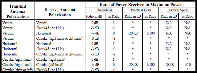
POLARIZATION Table 1 shows the theoretical ratio of power transmitted between antennas of different polarization. These ratios are seldom fully achieved due to effects such as reflection, refraction, and other wave interactions, so some practical ratios are also included.
Table 1. Polarization Loss for Various Antenna Combinations
* Approximately the same as theoretical Note: Switching transmit and receive antenna polarization will give the same results.
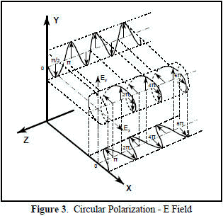
The geometric figure traced by the sum of the electric field vectors over time is, in general, an ellipse as shown in Figure 2. Under certain conditions the ellipse may collapse into a straight line, in which case the polarization is called linear. In the other extreme, when the two components are of equal magnitude and 90° out of phase, the ellipse will become circular as shown in Figure 3. Thus linear and circular polarization are the two special cases of elliptical polarization. Linear polarization may be further classified as being vertical, horizontal, or slant. Figure 2 depicts plots of the E field vector while varying the relative amplitude and phase angle of its component parts.
Figure 2. Polarization as a Function of Ey/Ex and Phase angle
For any antenna with an aperture area, as the aperture is rotated, the viewed dimension along the axis remains constant, while the other viewed dimension decreases to zero at 90° rotation. The axial ratio of an antenna will get worse as the antenna is rotated off boresight because the field contribution from the axial component will remain fairly constant and the other orthogonal component will decrease with rotation.
The sense of antenna polarization is defined from a viewer positioned behind an antenna looking in the direction of propagation. The polarization is specified as a transmitting, not receiving antenna regardless of intended use.
Optics people view an aperture from the front and therefore use the opposite reference.
The polarization of a linearly polarized horn antenna can be directly determined by the orientation of the feed probe, which is in the direction of the E-field.
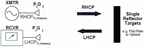
In general, a flat surface or sphere will reflect a linearly polarized wave with the same polarization as received. A horizontally polarized wave may get extended range because of water and land surface reflections, but signal cancellation will probably result in "holes" in coverage. Reflections will reverse the sense of circular polarization.
Wave propagation between two identical antennas is analogous to being able to thread a nut from one bolt to an identical opposite facing bolt.
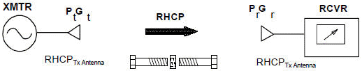
NOTE: This figure depicts an example only, all polarizations can be reversed. In either case, the antennas should be identical. Figure 5. Same Circular Polarization
NOTE: This figure depicts an example only, all polarizations can be reversed. In either case, the antennas should have opposite polarization. Figure 6. Opposite Circular Polarization
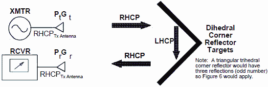
NOTE: This figure depicts an example only, all polarizations can be reversed. In either case, the antennas should be identical. Figure 7. Same Circular Polarization With Corner Reflector
An aircraft acts as both a corner reflector and a "normal" reflector so the return has mixed polarization. Most airborne radars use the same antenna for transmitting and receiving in order to receive the corner reflections and help exclude receipt of reflections from rain (single polarization reversal), however in doing so there is about a 5-9 dB loss from the ideal receiver case. It should be noted that the return from raindrops is attenuated by approximately 20 dB.
Table of Contents for Electronics Warfare and Radar Engineering Handbook Introduction | Abbreviations | Decibel | Duty Cycle | Doppler Shift | Radar Horizon / Line of Sight | Propagation Time / Resolution | Modulation | Transforms / Wavelets | Antenna Introduction / Basics | Polarization | Radiation Patterns | Frequency / Phase Effects of Antennas | Antenna Near Field | Radiation Hazards | Power Density | One-Way Radar Equation / RF Propagation | Two-Way Radar Equation (Monostatic) | Alternate Two-Way Radar Equation | Two-Way Radar Equation (Bistatic) | Jamming to Signal (J/S) Ratio - Constant Power [Saturated] Jamming | Support Jamming | Radar Cross Section (RCS) | Emission Control (EMCON) | RF Atmospheric Absorption / Ducting | Receiver Sensitivity / Noise | Receiver Types and Characteristics | General Radar Display Types | IFF - Identification - Friend or Foe | Receiver Tests | Signal Sorting Methods and Direction Finding | Voltage Standing Wave Ratio (VSWR) / Reflection Coefficient / Return Loss / Mismatch Loss | Microwave Coaxial Connectors | Power Dividers/Combiner and Directional Couplers | Attenuators / Filters / DC Blocks | Terminations / Dummy Loads | Circulators and Diplexers | Mixers and Frequency Discriminators | Detectors | Microwave Measurements | Microwave Waveguides and Coaxial Cable | Electro-Optics | Laser Safety | Mach Number and Airspeed vs. Altitude Mach Number | EMP/ Aircraft Dimensions | Data Busses | RS-232 Interface | RS-422 Balanced Voltage Interface | RS-485 Interface | IEEE-488 Interface Bus (HP-IB/GP-IB) | MIL-STD-1553 & 1773 Data Bus | This HTML version may be printed but not reproduced on websites. |
|||
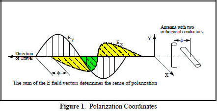 The polarization
of an electromagnetic wave is defined as the orientation of the electric field vector. Recall that the electric field vector is perpendicular
to both the direction of travel and the magnetic field vector. The polarization is described by the geometric figure traced by the electric
field vector upon a stationary plane perpendicular to the direction of propagation, as the wave travels through that plane. An electromagnetic
wave is frequently composed of (or can be broken down into) two orthogonal components as shown in Figure 1. This may be due to the arrangement
of power input leads to various points on a flat antenna, or due to an interaction of active elements in an array, or many other reasons.
The polarization
of an electromagnetic wave is defined as the orientation of the electric field vector. Recall that the electric field vector is perpendicular
to both the direction of travel and the magnetic field vector. The polarization is described by the geometric figure traced by the electric
field vector upon a stationary plane perpendicular to the direction of propagation, as the wave travels through that plane. An electromagnetic
wave is frequently composed of (or can be broken down into) two orthogonal components as shown in Figure 1. This may be due to the arrangement
of power input leads to various points on a flat antenna, or due to an interaction of active elements in an array, or many other reasons. 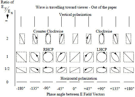
 For a linearly polarized antenna, the radiation pattern is taken both for a co-polarized and cross polarized
response. The polarization quality is expressed by the ratio of these two responses. The ratio between the responses must typically be great
(30 dB or greater) for an application such as cross-polarized jamming. For general applications, the ratio indicates system power loss due to
polarization mismatch. For circularly polarized antennas, radiation patterns are usually taken with a rotating linearly polarized reference
antenna. The reference antenna rotates many times while taking measurements around the azimuth of the antenna that is being tested. The resulting
antenna pattern is the linear polarized gain with a cyclic ripple. The peak-to-peak value is the axial ratio, and represents the polarization
quality for a circular polarized antenna. The typical RWR antenna has a maximum 3 dB axial ratio within 45° of boresight.
For a linearly polarized antenna, the radiation pattern is taken both for a co-polarized and cross polarized
response. The polarization quality is expressed by the ratio of these two responses. The ratio between the responses must typically be great
(30 dB or greater) for an application such as cross-polarized jamming. For general applications, the ratio indicates system power loss due to
polarization mismatch. For circularly polarized antennas, radiation patterns are usually taken with a rotating linearly polarized reference
antenna. The reference antenna rotates many times while taking measurements around the azimuth of the antenna that is being tested. The resulting
antenna pattern is the linear polarized gain with a cyclic ripple. The peak-to-peak value is the axial ratio, and represents the polarization
quality for a circular polarized antenna. The typical RWR antenna has a maximum 3 dB axial ratio within 45° of boresight.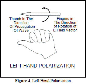 We frequently use "hand rules" to describe the sense of polarization.
The sense is defined by which hand would be used in order to point that thumb in the direction of propagation and point the fingers of the same
hand in the direction of rotation of the E field vector. For example, referring to Figure 4, if your thumb is pointed in the direction of propagation
and the rotation is counterclockwise looking in the direction of travel, then you have left hand circular polarization.
We frequently use "hand rules" to describe the sense of polarization.
The sense is defined by which hand would be used in order to point that thumb in the direction of propagation and point the fingers of the same
hand in the direction of rotation of the E field vector. For example, referring to Figure 4, if your thumb is pointed in the direction of propagation
and the rotation is counterclockwise looking in the direction of travel, then you have left hand circular polarization.