|
September 1934 Radio-Craft
 [Table
of Contents] [Table
of Contents]
Wax nostalgic about and learn from the history of early electronics.
See articles from Radio-Craft,
published 1929 - 1953. All copyrights are hereby acknowledged.
|
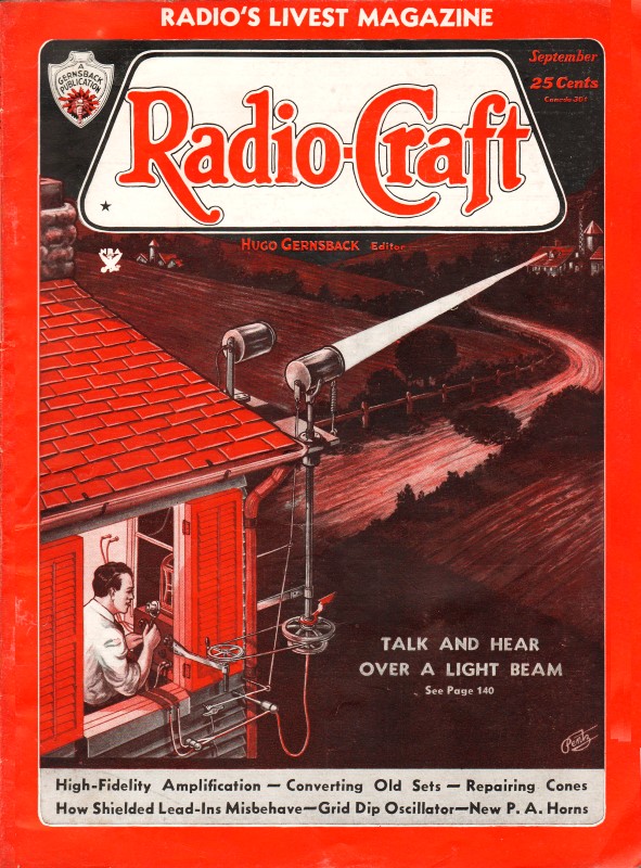
Here are the schematics, chassis
layout, and service info for the Howard Explorer Model W Deluxe 19 Tube All-Wave
Superheterodyne console style (sits on the floor) radio. The wooden cabinet
format is somewhat unusual in that the top is a flat surface rather than the
having more typical curvaceous lines that radios of the era sported. It looks a
lot like the models with built-in phonographs, where the top would tilt upward. The Radio Service Data
Sheets that were published in Radio-Craft usually seem to have more information
included than those published in other magazines, at least in the same era (1940-ish).
It might have to do with how much material is provided by the manufacturer rather
than a decision by the magazine editors. This one appeared in the September 1934
issue. Believe it or not, there are still people searching for such data. I
could not find an example of a real surviving Howard Explorer Model W Deluxe
radio.
Howard Explorer Model W Deluxe 19 Tube All-Wave Superhet Radio
Service Data Sheet
 (Uses single-purpose tubes to secure extreme
circuit stability: wavelength range, 13.6 to 2,142 meters; provides for either inverted-L
doublet antenna; neon resonance indicator; zero-beat oscillator; variable Q A.V.C.;
tone control; variable A.V.C. parallel push-pull output 245s.) (Uses single-purpose tubes to secure extreme
circuit stability: wavelength range, 13.6 to 2,142 meters; provides for either inverted-L
doublet antenna; neon resonance indicator; zero-beat oscillator; variable Q A.V.C.;
tone control; variable A.V.C. parallel push-pull output 245s.)
A 19 tube radio receiver in its home. Airplane-type dials are used; only the
tuning dial sector of the band in use is illuminated. as the band switch is turned.
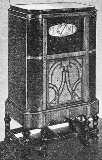
Schematic circuit of the A.F. amplifier and power pack chassis. There are 9 tubes
in this section of the instrument. A "theatre" type dynamic speaker is used,
Until very recently the general practice has been to utilize the new tubes at
their maximum capabilities. Consequently, a slight change in characteristics would
greatly affect the operation of the complete receiver. However, this 19 tube set
is designed to utilize its tube complement very conservatively, with the result
that great stability has been achieved which, after all, is a major factor in securing
satisfactory reception, especially on the short waves.
Note; it is inadvisable to attempt to realign the set except as a last resort.
The recommended procedure, only to be used by expert radio Service Men, is as follows:
To align the I.F. circuits feed the I.F. service oscillator test signal into
the control-grid of V2.
When aligning R.F., I.F., or oscillator circuits turn A.V.C. adjustment (slotted
shaft) to extreme left. The I.F. trimmers are very critical, greatly affect the
performance of the set, and must be carefully resonated.
 Aligning R.F. and Oscillator Circuits Aligning R.F. and Oscillator Circuits
Adjust A.V.C. control to extreme left position. It is unnecessary to remove the
set oscillator tube. Align the circuits only in the sequence given.
To align the set oscillator turn its trimmer all the way out and then select
the strongest signal when turning it in; set insensitivity near the center of the
dial will result if the wrong oscillator signal is used.
Bend the variable condenser plates for kc. dial alignment only in the broadcast
band. Before adjusting any band, make certain that the pointer of the station indicator
is set on the last black line when the dial is turned all the way to the left on
the broadcast band just above 0.55 (Maximum capacity of the variable condenser).
Long-Wave Band
Turn the band indicator to 0.15-0.35, set the dial to 0.35, and feed 350 kc.
into the antenna post. Resonate the trimmer (not green coded on the trimmer washer)
in the long-wave oscillator can. Align the R.F. and antenna stages. Reset dial to
just above 0.17 and resonate the green coded oscillator trimmer at 175 kc. Recheck
the 350 kc. setting.
Broadcast Band
It is necessary on the broadcast band only, that a metal plate with holes in
line with the trimmer nuts be used so that the circuits are not detuned when the
regular base plate is screwed back on.
Turn the band indicator to broadcast 0.55 to 1.5, set the dial to 1.4, and feed
in 1,400 kc. Resonate trimmer 14, R.F. trimmer 7 and the antenna trimmer (knurled
knob extending from top of antenna coil can). Now rotate dial to 0.55 and resonate
trimmer 10 at 550 kc. Re-check the setting at 1,400 and bend plates of variable
condenser at 950 and other points where necessary to secure kc. reading on dial.
Short-Wave Band No.1
Turn band indicator to 1.5 to 3.5, set dial to 3.5, and feed in 3,500 kc. service
oscillator signal. Resonate trimmer 13, R.F. trimmer 6 and antenna trimmer 3. Rotate
dial to 0.55 on broadcast hand. (The short-wave dial calibration may be inaccurate
at this point and the 0.55 figure corresponds to 1.5 on short-wave band No. 1.)
Feed in 1,500 kc. and resonate trimmer 9. Recheck at 3,500 kc.
Short-Wave Band No.2
Turn band indicator to 3.5 to 9, set dial to about 8.9 (due to off-calibration
this corresponds to 8.5), and feed in 8,500 kc. Resonate trimmer 12, R.F. trimmer
5 and antenna trimmer 2. Rotate dial to 3.5 and resonate trimmer 8 at 3,500 kc.
Recheck at 8.5 (8.9).
Short-Wave Band No.3
Turn band indicator to 9 to 21, set dial to 20, and feed in 20,000 kc. Resonate
oscillator trimmer 11, R.F. trimmer 4 and antenna trimmer 1. The alignment at 9
is obtained by use of the fixed condensers which should not require change. To insure
band sensitivity in the region of major foreign program reception, turn the dial
to 12 and resonate antenna coil trimmer 1 at 12,000 kc.
Note that since all adjustments are made with the A.V.C. inactive, extreme care
must be used to attenuate the input signal low enough so that there will be no overloading
of tube amplifiers while making adjustments.
After these high-frequency adjustments have been made, the service oscillator
setting should be advanced 930 kc. and the output signal strength considerably increased;
non-reception of the image signal indicates incorrect set oscillator adjustment.
For example: a service oscillator signal of 20,930 kc. should be perceptible at
20 on the dial after alignment to 20,000 kc.
Beat Oscillator Adjustments
Turn the main dial to receive a service oscillator signal of 4,800 kc., and make
sure that the band on the "beat oscillator" (Frequency Meter V17) falls on 1.5 when
the 2 gang condenser is at full capacity.
Turn Osc. Sw. to the right ("Mod."), and frequency dial to 4. Resonate the trimmer
on the 2 gang condenser to main dial setting. Turn band indicator switch to short-wave
band No. 1 (1.5 to 3.5), set main dial to where 1,500 kc. comes in, turn frequency
dial to 1.5, and then resonate trimmer 15.
A.V.C. Adjustment
Connect one side of a high-resistance voltmeter to A. V.C. potentiometer terminal
which connects to the "high" side of the 0.2-meg. resistor and to the 0.1·mf. fixed
condenser, and the other (positive) to chassis ground.
Adjust the receiver for reception of a signal intensity of 3,000 to 4,000 micro-volts,
and vary for maximum voltmeter reading, in a given locality, the adjustment in the
top, next to the neon adjustment, of the coil can assembly in the upper right-hand
corner (facing rear of tuner).
In certain localities close to a broadcast station it may be necessary to readjust
the A. V.C. (slotted shaft) control. Exactly resonate the receiver. Then, if the
station's signals sound "fringy" or rough, turn the control to the right only sufficiently
far to correct this condition.
Neon Tuning Indicator and Q.A.V.C.
Facing the back of the tuner chassis, extending through one of the tall shielded
assemblies in the upper right-hand corner, will be found a small, black knurled
knob used to adjust the neon resonance indicator. It is advantageous to be able
to set this adjustment if excessive fading is experienced due to locality. Adjust
the receiver dial to a powerful station during the time of day in which it is received
strongest. Then turn the neon adjustment until the light just fills the opening
in arrow dial. Readjust the tuning dial of the receiver; should the light become
more brilliant, leave the dial at the point of highest brilliancy and again readjust
the neon indicator until it just fills the arrow opening. (This adjustment need
be made only when the set is installed.)
Since the interstation noise suppression system or Q.A.V.C. is a proportional
function of the neon light, the Q.A.V.C. system will be correctly adjusted.
Note that the neon light system is not intended to work on the short-wave stations.
However, it will usually indicate resonance to more powerful signals.
Resistor X is an oscillator suppressor in short-wave band No.3. Its value is
determined by individual requirements.
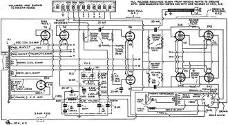
Locations of trimmer condensers in the new 19 tube all-wave superheterodyne.
This illustration furnishes the necessary information to complete the data In the
text.
Schematic circuit of the tuner chassis. There are 10 tubes in this unit. The
2·gang condenser mentioned in the text is located at the right of oscillator V17.
Posted March 27, 2023
(updated from original post
on 10/6/2015)
Radio Service Data Sheets
These schematics, tuning instructions, and other data are reproduced from my
collection of vintage radio and electronics magazines. As back in the era, similar
schematic and service info was available for purchase from sources such as
SAMS Photofacts, but these printings
were a no-cost bonus for readers. There are 227 Radio Service Data Sheets as of
December 28, 2020.
-
AMRAD
Model 81 "Bel Canto"
-
GE
Model 250 Radio Service Data Sheet
- Hoffman
Model A300
- Emerson
Model 505
- Olympic
Models 6-501, 6-502, 6-503
- Radiola
Models 61-5, 61-10
- Farnsworth
Models ET-060, ET-061, ET-063
- General
Electric Model 321
-
Garod Model 6AU-1
- Truetone
Model D4620
- Westinghouse
Model H-148
- Wards Models
54BR-1501A, 1502A
- Majestic
Models 8S452, 8S473
- RCA Models
Q22A, Q32
- Zenith Model
5G003ZZ
- Mantola Models
92503 and 92504
- Emerson Model
508 Series 8-7434351 and Up
- Belmont Model
A-5D118
- Wards Model
74BR-2707A
- Crosley Model
56TP-L
- Admiral Model
7C60 Chassis 6B1
- 336
Belmont Radio Model 6D111, Series A
-
333 General Electric Models 100, 101, 103 and 105
- RCA Victor
Models 54B1, 54B-N, 54B2, 54B3 Radio Data Sheet 335
-
National Union "Presentation" Radio Model G-619
-
Zenith Radio Models 8H032, 8H033, 8H050, 8H052, 8H061
-
General Electric Farm Radio Model 280
-
Admiral Model 6RT44-7B1
-
Montgomery Ward Airline Model 04BR-1105A Radio
- Belmont
Model 678 Auto-Radio Set
- Sentinel
Model 217-P Portable Radio Set Radio
- Remler
Model No. 36 Dual-Wave Auto-Radio
-
Stromberg-Carlson No. 82 All-Wave Receiver
-
Majestic A.V.C. Model 290 Chassis
- FADA 9 Tube
Model 190 "Metal" All-Wave
- RCA Victor
Models 9T and K2 9-Tube, 5- to 566-Meter
-
Motorola "Golden Voice" Model
-
RCA Victor Model H-6
-
Simplex Model TA
-
Automatic "Magic Eye" Model A1
- Silvertone
Models 4488 and 4588 (Chassis No.101412) and 4488A and 4588A (Chassis No. 101412A)
- RCA Victor
Model M109 "De Luxe" 7-Tube Auto-Radio Receiver
- Crosley Model
6625 6-Tube 3-Band Receiver
- International
Model 77 Series 7-Tube Dual-Band Receiver
- Belmont
Model 6D121
-
General Electric Models 60, 62
- Admiral
Model 7C64
-
Radiola "28" Super and "104" Power Speaker
- Sonora
Model TW-49
-
Stromberg-Carlson Models 1020, 1120, Series 10
- Air King
Model 4604D
- Sparton Models
526, 526X, 526PS
- Truetone
Model D2624
- Admiral
Models 6EI, 6EIN
- Detrola Models
571A, 571B
-
General Electric Model 250
- Howard Model
920
- Colonial
Model 652 5-Tube Broadcast-Short-Wave
-
Fairbanks-Morse
9-Tube All-Wave Model 91
-
International Model 500 5-Tube Dual-Range Battery
- Emerson Model
678 "Auto-Dynamic" 5 Tube
-
Stromberg-Carlson
Nos. 230 and 231 Series
- Atwater
Kent Model 649 All-Wave
-
Howard Model G-26, and "Airplane 4" Model AA25
-
Montgomery Ward "Airline" Series 7GM 7-Tube High-Fidelity Receiver
- RCA
Victor Model T5-2 5-Tube, 2-Band A.C. Superheterodyne Receiver
-
Majestic
"Models 50," "51" and "52"
-
Bremer-Tully Model 7-70 and 7-71
-
General
Electric Model M-49 4-Tube Radio-Phonograph Dual-Wave Superheterodyne
- RCA-Victor
Radiola "Superette" Model R7 Superheterodyne
- Crosley Model AC-7
and AC-7C
-
Westinghouse
"Columnaire" Models WR-8 and WR-8-R (Remote Control)
-
Characteristics
of Metal Tubes - and Other "Octal" (8-Prong) Base Types
- Kolster K20,
K22, K25, K27 and K37 Six-Tube Receivers
-
Stromberg-Carlson
Nos. 62 and 63, 8-Tube High-Fidelity Chassis
- RCA Model
103, 4-Tube A.C. Compact Dual-Wave
- FADA "Special"
Model 265-A and FADA "7" Model 475-A
-
General Electric Model C-62 6-Tube Battery
- Emerson
5A Automotive
- Zenith
666 Automotive
- Motorola
100 Automotive
-
Crosley
Roamio 4-A-1 Automotive
-
American-Bosch
524A Automotive
- Crosley
Model 1316 (in Model 167 Console)
- RCA Victor
"High-Fidelity Electrola," Model R-99
- AMRAD
Model 81 ("Bel Canto" Series) Receiver
-
Fada 103 Fadalette, Stewart-Warner Series 108, DeWald 54 Dynette Sets
- RCA
Victor R-27 and Philco 53 Ultra-Midget A.C.-D.C. Radio Receivers
-
Majestic Models Fairfax and Sheffield 8-Tube
- Stromberg-Carlson
No. 29, 9-Tube Superhet
-
International Kadette Model 400 4-Tube Battery-Operated Superhet
- RCA Victor
Model 5M 5-Tube Auto Superhet
-
Majestic Model 11 Short-Wave Converter
-
Silver-Marshall
Model 727-DC Battery-Operated Superheterodyne
- RCA
Victor Model VHR-307 Home Recording - Phono-Radio Combination
-
Delco 32-Volt Radio Receiver Chassis Models RA-3, RB-3 and RC-3
- Majestic
Chassis Models 380 A.C. T.R.F., and 400 A.C.-D.C. Superheterodyne
- General
Motors S1A, S1B
- Admiral
Model 7C63, Chassis 7C1
- Westinghouse
Model H-133
- Arvin
Models 150TC, 151TC
- Kadette Model
90 Duplex
-
RCA-Victor "Magic Brain" Model 281
- Grunow
11A Chassis 11-Tube All-Wave Superheterodyne
-
Sears, Roebuck & Co., Silvertone "Rocket" Models 6110 and 6111
-
General Electric Model GD-52
-
Zenith Models 6D302, 6D311, 6D326, 6D336, 6D360
-
Allied Radio, Knight Model E10913
- Arvin Model
140P
- Emerson
Models 501, 502, 504
- Crosley
Model 56TD-W
- Hoffman
Model A500
-
Stewart-Warner
Model 9003-B
-
Zenith Models 6D014, 6D029
- Coronet
Model C-2
- Sparton
Models 7-46, 7-46PA, 8-46, 8-46PA
-
Stewart-Warner Models 9001-C, D, E, F
-
Zenith Models 5D011-5D027
- Bendix Models
636A, C, D
- ECA Model 108
-
International Model 66 and 666, 6-Tube Superhet
-
Ford-Philco
Radio, Model FT9, 6-Tube Auto-Radio Receiver
- Howard
Explorer Model W Deluxe 19 Tube All-Wave Superhet
- RCA Victor
Portable Table Electrola Model R-95
- Atwater
Kent Model 305Z 5-Tube 32 V. D.C. Superhet
- Kadette
Jewel Model 40 Chassis 3-Tube Ultra-Midget Receivers
-
General Electric Model N-60 6-Tube Auto Superheterodyne
-
Sparton Model 40 6-Tube T.R.F. Automotive Receiver
-
Clarion "Replacement" Chassis, Model AC-160 A.V.C. Superheterodyne
- Emerson Models
20A and 25A
- General
Electric K-40A
- Pilot Model
B-2
- RCA-Victor
Radiola Model M-30 Automotive Radio
- Motovox
Models 10A All-Electric and 10E Battery-Operated "Moto-Tetradynes"
-
Kennedy Superheterodyne Short-Wave Converter
- RCA
Victor Model R-78 B1-Acoustic 12-Tube
- Philco
Model 15 Series, 11-Tube Superheterodyne Chassis
-
Zenith Challenger Model 740
-
Sparton
Selectronne Receivers Models 1068 and 1068X
- Fada Model
155 Super Fadalette A.C.-D.C. Set
-
Clarion De Luxe Models AC-280 and 25-280
-
Crosley Model A-157 (River Roamio) Auto Radio
- Philco Model
'37-116 Codes 121 (Shadometer) and 122 (Dial Tuning)
-
Arvin Model 28
-
Philco Model 818
-
Fada Model 266 Motoset
-
Bosch Models 736, 737, 738
- RCA-Victor
Model 15U, Radio-Phonograph
- Sparton
Models 566 ("Bluebird" Mirror), A.C.-D.C. 5-Tube 2-Band Midget Superhet
- Atwater
Kent Model 776 6-Tube Auto Radio
- Stromberg-Carlson
No. 61 4-Band 7-Tube A.C.-D.C. Receiver
- Arvin Model
182TFM
- Crosley
Model 58TK
- Westinghouse
Model H-165
-
General Electric Models G-105 and G-106
- Silvertone
"F," "FF," "G," "H," and "J"
-
Stewart-Warner Model 03-5A1 to 03-5A9 (Chassis 03-5A) Senior Varsity Radio
- Radiola Models
61-6, 61-7
-
Westinghouse
Models H-104, H-105, H-107, H-108
- Farnsworth
Models EC-260, EK-262, EK-263, EK-264, EK-265
-
United
Models 980744, 980745
-
Stewart-Warner (R-127 Chassis) Models 1271 to 1279 All-Wave
- ERLA Model
4500 Dual-Wave T.R.F. 4-Tube A.C. Receiver
- Clarion No. TC-31
5-Tube A.C.-D.C. Superhet.
- Detrola Model
105C 5-Tube Dual-Band A.C.-D.C.
- Zenith
6-Tube All-Wave Chassis No. 5634
- RCA Victor
Model 261, 555 to 107 Meter
- Philco
Model 38-116; Code 125
-
Stewart-Warner "Ferrodyne" Chassis Model R-136
-
American-Bosch
Model 43OT 5-Tube 3-Band Superheterodyne
- RCA
Victor Model C9-4 9-Tube 3-Band Superheterodyne
- Kennedy "Model
826B" Combination Receiver
- Steinite
50-A and 102-A
- Pilot Model
63 All-Wave 6-Tube Superheterodyne
- Stromberg-Carlson
No. 69 4-Tube All-Wave Superhet. Selector (Converter)
- RCA
Victor Model 102 4-Tube A.C.-D.C. T.R.F. Receiver
- Bosch Models 60
and 61
-
Atwater Kent Models 30, 33, 35, 48 and 49
- Crosley Model
120 Senior Superheterodyne (Pliodynatron) Chassis
-
Columbia Screen-Grid 8 Receiver
-
General Electric Models A82 and A87, 8-Metal-Tube All-Wave A.C. Superhet.
- Colonial
31 and 32 D.C.
- Zenith 5-Tube
Triple-Wave Chassis nos. 5508 and 5509
- Remler Model
46 ("Scottie")
- General
Electric FA-60 and FA-61
-
Stewart-Warner
Series 900
-
Howard
Model B-5 (715), Series 1 and 2 (Sheaffer Radio-Clock-Pen Desk Set)
-
Ford-Philco Car-Radio Models F-1440 and F-1442
-
Brunswick Model 31 Combination Radio and Panatrope
- Emerson Models
38, 42 and 49, 6-Tube Dual-Wave (Chassis U6)
-
General Motors Chevrolet No. 601574 Automotive
-
RCA Victor M-104 (and M-108) Automotive
- Arvin-Ford
17-A Automotive
-
Westinghouse Model WR 207 & WR 208 5-Tube Dual-Band Superheterodyne
- Radiolas
"Super VIII" (AR-810, "Semi-Portable" (AR-812), 24 and 26
- Howard Model
45 A. V. C.
- Majestic
Model 25
-
Galvin Motorola Model 61
-
Arvin Model 6
- Admiral
Models 7T06, 7T12
- Garod Model 5A1
- Hoffman Model A301
-
Knight Model E10716 Battery Portable
- Arvin Models 555,
555A, 552N, 552AN
- Grantline Models
605, 606
- Truetone Model
D2616
- Belmont Model
5D128
- Arvin Models 444,
444A
-
International Kadette Model 1019
-
Stewart-Warner Models 97-561 to 97-569
- General
Electric Model 280
- Zenith Models 5R080,
5R086
- Truetone Models
D1747, D1748
-
Crosley Roamio Automotive T.R.F. Models 90, 91, 92
-
Crosley Roamio Automotive Superheterodyne Models 95, 96
-
Wells-Gardner Series 062
-
Emerson
Model AZ-196
- Belmont Model
5P19
- Crosley
Fortyfive
- Crosley Model
56FC
-
Emerson
Models 507, 509, 518, 522, 535
- Garod Model 6AU-1
- General
Electric Models 219, 202, 221
-
Crosley "Chairside" Model 567
-
Belmont Model 408 Battery "Farm"
- Wards Model
74BR-1055A
- Farnsworth
Models EK-081, EK-082, EK-083, EK-681
- Philco
Model 200-X Radio
-
Admiral "Aeroscope" Models 161-5L, 162-5L and 163-5L
- Philco
Model 59, 4-Tube A.C. Midget Superheterodyne
- Zenith
Farm Model 6V 27, 6-Tube Superhet
- Ward 10-Tube
All-Wave High-Fidelity Superhet, Series ODM
-
Philco-Packard
Deluxe
-
Canadian
Westinghouse Model 175
- Crosley Model
1155
- Philco Models
39 and 39A
-
Arvin Model 35 8-Tube Car-Radio
- Hetro
Air-Ace Series M
- Westinghouse
Models H-161, H-168, H-168A
- Garod Model 5A4
- Arvin Models 152T,
153T
- Belmont Model 5240
- Mantola Models 92505,
92506
- General Electric
Models 102, 102W, 107, 107W, 114, 114W, 115, 115W
- Crosley Model
555 (A.F.M.)
- Crosley Model
515 (Fiver)
- Crosley Model
425 (Travo)
-
Firestone-Stewart-Warner Model R1332
- Fairbanks-Morse
Model 81 "Farm" Set
- Clarion Model
423, 470, 471, 472, 480
-
International Radio Corp. Model 90
- Belmont Model
578 Series A
|