What's Your EQ?
|
|||
The Radio-Electronics magazine folks who thought up the May 1961 issue's "What's you EQ?" (Electronics Quotient) questions were in rare form; they called it "a department of mental calisthenics." The first two of three were real posers, both with multiple correct answers. Readers obliged the challenge with many proposed solutions, so many that the June and July issues were required for providing enough print space. The third, while fundamentally simple, can throw you for a loop if you overthink the problem. I didn't come up with their solution. Going with the not overthinking approach, mine suggested that there is nothing in the black box (i.e., open circuit) and that the internal resistance of the voltmeter was 10 Ω, which would cause 1 A to be drawn from the 10 V source while registering 0 W on the wattmeter. That's the solution with an absolute minimum of thought. None of the readers - at least those who wrote in - came up with that. What's Your EQ?We are starting this month a department of mental calisthenics - an opportunity for you to see just how fast your brain can turn corners. So that everybody can have a chance, the exercises are graded into three groups. The first will be practically on the engineering level, the second something for the good practicing TV technician and the third for the beginner. Next month we will publish possible solutions to the first two questions, plus the answer to the third. Since the first two problems will probably have more than one good solution - there are more ways than one to lick a design problem, and a single set of symptoms in a TV set may have more than one cause - we are asking our readers to send in what they consider the best solutions for the first two. Mail your answer to Puzzle Editor, Radio-Electronics, 154 W. 14th St., New York 11, N.Y. Radio-Electronics invites its readers to send in their own original brain-teasers. We will pay $10 for each one used.
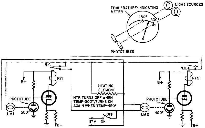
Photo-Relay Circuit Two photo-relay circuits are to be used to maintain the temperature of an oven between the limits of 450° and 500°. The phototubes are illuminated through two openings in the temperature-indicating meter of the oven as shown in the drawing. The oven is heated by a 117-volt heating element which should turn off when the meter pointer blocks the opening at 500°, and turn on again when the pointer drops back to 450° The 50° dead zone is used to limit the number of relay operations per hour (which would be much higher in a single phototube system). What circuit arrangement will provide the desired temperature regulation without requiring any manual controls except an on-off switch in the power line? The circuit must work from a "cold" start when the pointer of the meter is still below the 450° level. - Ed Bukstein
Service Stinker No.1 Symptoms: No picture. Slight hum in sound, resistor R1 burns out immediately. 1/2-watt size is correct; other sets work with this value. Dc voltages normal. No shorts to ground. Tubes all replaced. Question: What is burning R1 out in such a hurry? - Jack Darr
Black Box
A black box is connected to a power source that supplies it with 10 volts and 1 ampere, as indicated by a conventional voltmeter and ammeter. Yet an equally conventional wattmeter also connected across the input of the black box shows that no power is being supplied to the load. What is in the black box? Quizzes from vintage electronics magazines such as Popular Electronics, Electronics-World, QST, and Radio News were published over the years - some really simple and others not so simple. Robert P. Balin created most of the quizzes for Popular Electronics. This is a listing of all I have posted thus far.
Answers to What's Your EQ? (from June 1961) Here are the answers to last month's questions. We have not been able to print any answers from readers due to time squeeze, but, if any outstanding solutions come in, we will run them next month. Note: Additional responses from July 1961 at are the bottom. Photo-Relay Circuit
1. Both relays are actuated by a decrease in light. 2. RY1 - in 500° circuit - has normally closed contacts. 3. RY2 - in 450° circuit-has normally open contacts. 4. When RY1 opens, voltage is removed from the heater and from LM1. 5. When RY2 closes, voltage is applied to the heater and to LM1. Operation: Assume temperature is between 450° and 500°. 1. The heater and LM1 are on. 2. Light falls on both phototubes. 3. When the temperature reaches 500°, light to the phototube controlling RY1 is blocked. RY1 opens, removing voltage from the heater and LM1. 4. The heater and LM1 remain off because RY1 is operated by a decrease in light level. 5. As the temperature reaches 450°, the hole is blocked, RY2 pulls in and the normally open contacts close, applying power to the heater and LM1.
Although voltage measurements and current measurements show everything to be lovely as far as dc is concerned, a scope reading taken across R1 shows something like 300 volts peak-to-peak ripple! The exceedingly low-impedance path to ground provided by the 10-μf capacitor causes a tremendous pulse current to flow through the little resister, burning it out very rapidly. Cause: completely open input filter capacitor in the power supply! Both in fact. The negative connection had opened. This would have been cleared quickly had a scope been used on the B-plus, instead of relying solely on dc voltage measurements.
Black Box
But the contacts open and close in such rapid sequence that conventional meters cannot follow the voltage and current patterns, so take up positions between zero and the peak values. Since the wattmeter needs both voltage and current to show any indication, and since there is no voltage when there is current and no current when there is voltage, it remains at zero.
More on May (from July 1961) The Photo-Relay Circuit Problem, published on page 56 of the May issue, was to maintain, with photo-relays, the temperature of an oven between 450 and 500°. The pointer of a meter would block off light to the phototubes at those points. The equipment was to work from a cold start. Fig. 1 shows the setup and the circuit used by Ed Bukstein, who proposed the problem. Interestingly enough, none of the solutions received at the time of writing duplicate Bukstein's circuit exactly. The closest thing is a sort of complementary circuit (the relays are activated by light, not by its interruption) sent by 1. S. Kerstetter of Lansford, Pa, (Fig. 2). It depends, however, on relay B operating faster than relay A. The heating element is connected in circuit and B locks in through its contacts 1 and 2. Then A operates, opening the original circuit through B. The heater circuit will now remain closed till the current through B is cut off when the phototube is blocked at 500°. The pointer falls back to 450°, interrupts A, closes the circuit to B through its back contacts, and the cycle starts again. A circuit differing only in detail was proposed by electronic technician and TV repairman J. E. Michaud of Notre-Dame-du-Lac, Quebec. Mr. Michaud also proposed a one-relay circuit. It would, however, have required a special modification of the meter, with a thin metal plate instead of a pointer, so that the 450° hole would remain closed till the pointer reached the 500° point. Kenneth A. Piletic of La Salle, Ill., uses a different approach. Both photo-tubes are connected to the coil of relay 2 (Fig. 3). When the line switch is closed, the element is heated through normally closed contact 1 of relay 1. At 450°, V1 goes into action, drawing current and closing circuits 1 and 2 of relay 2. The heater is now supplied through normally open contact 1 of relay 1. Relay 2's coil is locked in through contact 3, and relay 1's coil is locked in through its contact 1 till ac power is turned off. When the pointer reaches 500°, V2 draws current, dropping the voltage across the load resistor enough to de-energize relay 2. Since relay 1 is locked in, the heater circuit remains open till the 450° point, when relay 2 closes again. Relay 1 is merely the cold-start device; relay 2 does all the work. A proposal to use one relay and tube, which looks as though it should work, was submitted by Leonard Kasday of Flushing, N. Y. The phototubes (V1, V2) (Fig. 4) form a voltage divider across the grid of the thyratron. Resistors R1 and R4 are so selected that V3's grid is negative enough to keep the tube from firing. When the temperature reaches 500° V2 is cut off, its resistance rises to practically open circuit, and V3's grid goes positive through R1, R3 and V1. The relay is pulled in, opening the heater circuit and applying a positive bias to V3's grid on positive half-cycles. The relay remains energized till, at 450°, V1 is cut off and V3's control grid again goes negative, releasing the relay and turning the heater on. Two other 1-relay circuits were proposed. They might well have operated, with proper selection of components, but were not as clearly worked out as the one just described. A few circuits included latching relays. (This might be the simplest and most efficient approach.) One ingenious circuit, by John Jarvis, University of Florida, used an ac and a dc relay for on-off control. But the great majority of circuits included three or more relays. A few went beyond three, and one used five. Fig. 1 -Mr. Bukstein's original circuit. Relays are actuated by decrease in light. Fig. 2 - One of the simplest circuits. Fig. 3 - Another effective solution. Fig. 4 - This circuit uses one relay. Most striking feature of the solutions to the photo-relay problem was the sophisticated nature of some of the entries. At least two were presented as finished engineering drawings, with all constants including ohm age of relay coils. One even named model numbers and tube types - included all the information necessary to buy the parts and construct the device. Unfortunately, some of the best prepared solutions were not entirely clear - the author expected to be read by another relay engineer. Possibly more than one good solution was not understood, due to unfortunate drawing and incomplete description. Service Stinker No. 1 In spite of the statement: no shorts to ground, most readers decided that the cathode capacitor was shorted. A small number - less than half a dozen - pointed out the correct answer, an open filter capacitor, and one reader pointed out that a shorted voice-coil winding or too-low output impedance might cause the tube to draw enough excess current to burn out the 470-ohm resistor. That Black Box
Posted September 18, 2023 |
|||