Radio Inventions of Lee de Forest
|
|||||
As is the case with most genius inventors who change the world, Lee de Forest's contribution to the world of electronics neither began with nor ended with his invention of the Audion amplifying vacuum tube. As detailed in many of the other articles published in the January 1947 edition of Radio-Craft magazine that commemorated the 40-year anniversary (seeToC), de Forest's path from a simple open flame type of demodulator to the ultimate design of the evacuated glass-encased Audion tube with plate, control grid cathode, and heater element required many years of trial and error. The stories were so captivating that I actually read every article in this edition. Eventually, I will have all of them posted. This particular piece by Fred Shunaman reports on some of the many other innovative, patented inventions of de Forest such as antenna transmission lines (twin lead and coaxial), radio signal detectors (his primary field of study), antenna de-icing equipment, a direction-finding antenna, vacuum tube based modulators and demodulators, a regenerative circuit, and more. Radio Inventions of Lee de Forest By Fred Shunaman
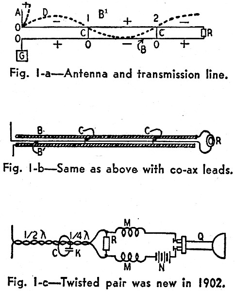
Fig. 1-a - Antenna and transmission line. Fig. 1-b - Same as above with co-ax leads. Fig. 1-c - Twisted pair was new in 1902.
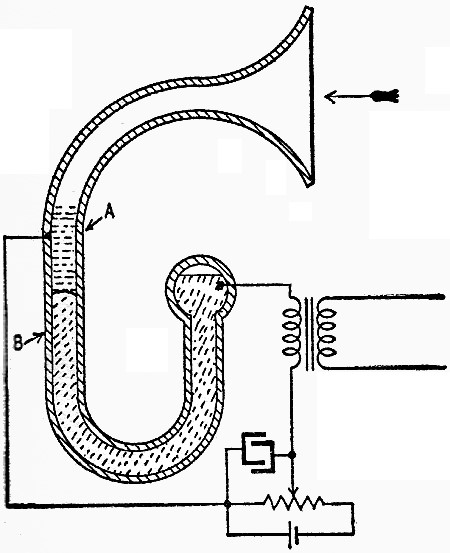
Fig. 2 - Early metal-oxide radio detector.
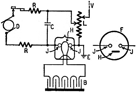
Fig. 3 - Alternating-current transmitter.
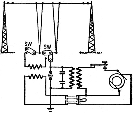
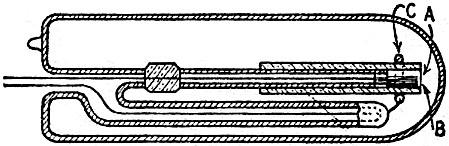
Fig. 4 - Device for ice-freeing antennas.
Fig. 5-a - Two-plate directional antenna.
Fig. 5-b - Early direction finder patent.
Fig. 5-c - A single-wire direction finder.
Fig. 5-d - Almost a loop direction finder.
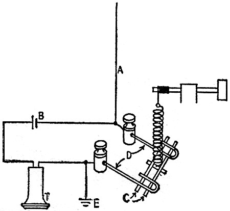
Fig. 6 - Earliest de Forest radiophone.
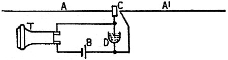
Fig. 7-a - First transmitter with a tube.
Fig. 7-b - Modulator is a grid audion.
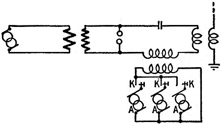
Fig. 8 - Transmitter for music-by-radio.
Fig. 9 - This 1907 three-tube heterodyne receiver had the first stage shielded.
Fig. 10 - A magnetic modulator circuit.
Fig. 11 - Section of quenched spark gap.
Fig. 12 - The first regenerative circuit.
Fig. 13 - Audion receiver with grid leak.
Fig. 14 - Multiple-grid tube transmitter.
Fig. 15 - Variation of the above circuit.
Fig. 16 - An ornamental receiver is the object of this table-lamp-radio patent. The fame of de Forest as the inventor of radio's most fundamental component has obscured his important work in the radio field as a whole. Many well-informed persons are not aware that he was the inventor of the transformer-operated spark transmitter, the quenched gap used on many shipboard installations till 1940,and the metal radio tube. A few more know that he holds the original patent on regeneration and that he was the inventor of the grid leak. His 1903 patents on r.f. transmission lines cover practices not fully put into use till two or three years ago. Dozens of other patents cover useful improvements in the radio art, or point the way to further progress in radio invention. De Forest's radio patents date back at least as far as 1902, when he was working on an early type of detector he called a responder. Opposite in action to the coherer, it consisted of two metal plugs sealed in a glass tube with a "suitable" solution between them. It was connected in a local battery circuit, as well as to the antenna system. "Little trees and branches" of metal were built up between the two plugs by electrolytic action, bridging the gap and reducing the resistance of the circuit. A signal on the antenna broke down these little bridges, raising the resistance of the circuit. De Forest called his detector an anti-coherer, and abandoned it only to work with the long series of "heat detectors" which culminated in the audion. Transmission Lines Startlingly modern are the antenna feed-line systems described in Patent No. 730,246, filed March 8, 1902, and granted June 9, 1903. Fig. 1-a shows a quarter-wave vertical antenna A and ground G, with a parallel-wire feed-line, BB' running to the responder or detector R. Bridges CC connect the lines together at half-wave intervals, to short out signals of unwanted frequencies. The broken line D indicates the voltage wave along the line and signs indicate the polarity. Fig. 1-b is a coaxial cable version of the same system. Twisted pair is shown in Fig 1-c. Standing waves were expected on the twisted pair, and bridges C are shown. MM are choke coils and Q a telephone. A local battery N is used with the Responder. The year 1902 saw de Forest busy on other important inventions. Among these was a metal-oxide detector, Patent No. 770,228. Two steel needles, C in Fig. 2, are held by a spring against two aluminum pins, DD. Means for adjusting the spring tension is provided, and the effect of the oxide coating on the aluminum is specifically mentioned, though it is stated that other metals may be used. Two important patent applications were filed in June, 1903. One of these was the transformer-operated spark transmitter (Patent No. 749,435), shown in Fig. 3. Induction coils with their vibrators and low-voltage contact points were troublesome and to tended to set a ceiling on transmitter power. As shown in Fig. 3, a gas-engine-driven alternator G supplied current to a low-voltage 1-to-1-ratio transformer T. A key C was placed between this transformer and high-voltage transformer T1. Choke coils K prevented r.f. surges from backing into the low-frequency lines. The oscillating circuit consisted of gap S, capacitors L, and antenna and ground A and E. This invention made the spark transmitter a reliable and powerful instrument, and induction coils disappeared except in low-powered experimental apparatus. The second invention of June, 1903, was a device for clearing ice from antennas, Patent No. 750,181. As shown in Fig. 4, this was a method of passing a high current at low voltage through part of the antenna, thereby heating it and melting off the ice. Switches connect either the transmitter or the ice-melting equipment to the antenna, paralleling the lead-ins to the spark gap and separating them across the low-voltage transformer secondary. Simultaneous Operation Break-in operation of wireless stations was another of de Forest's June, 1903, patents (No. 749,434). Two aerials were to be used, connected to two motor-driven commutators on the same shaft. Transmitter and receiver were thus alternately connected to their aerials. The patent suggests that the commutator rate at each station be different, with one interrupting at 40 times per second and the other at 60 (for example), so that the two cannot drift accidentally into synchronism, with both transmitters and both receivers on the air at the same time. A more modern break-in system is covered in Patents No. 827,523 and 827,524, issued in 1906. A contact on the end of the telegraph key disables the receiver during transmission. The detector is shorted in one form, and in another the anode of the then-popular electrolytic detector is lifted out of the liquid with which it is normally in contact. This patent shows gaps between the receiver and ground, to short heavy static charges to earth. An anti-static antenna system is proposed in Patent No. 759,216, application for which was filed May 14, 1902. Two antennas were connected to a single detector in such a way that one would neutralize or "buck" the other. One antenna is tuned to the frequency of the desired signal, the other left untuned. Atmospheric discharges, which would affect both antennas equally, were expected to balance out and produce no response in the detector circuit. The desired signal would produce a much stronger signal in the tuned circuit than in the untuned one, and therefore would be detected. Patent No. 894,378, applied for in 1903, shows a two-antenna system used for a different purpose. Signals were transmitted simultaneously on two frequencies. Receivers on each frequency were so adjusted that the combined signal from the two antennas would be just strong enough to operate the detector. The system was expected to reduce interference but there is no reason to believe that a very strong signal on one of the tuned frequencies would not upset the system. Radiocompass Patents An early direction finder is described in Patent No. 771,818 (applied for May, 1904). De Forest had already pointed out in his 1902 patent on transmission lines that a two-plate antenna would be directional, since radiation would be at a minimum in a direction edge-on to the plates (Fig. 5-a). The 1904 patent includes a flat plate (A in Fig. 5-b) on pivots C, an electrolytic detector . D, battery B, and telephone T. With the plate turned broadside to a signal, reception would be at a maximum. Edgewise on, signal pickup would be at a minimum. A light wire frame of vertical wires could be substituted for the metal plate, which was 6 x 15 feet in size in the inventor's experiments. A later patent (No. 771,819) shows what looks like a directional dipole, AA' of Fig. 5-c. Being "short as compared with one-quarter wavelength of the received waves" however, it received its strongest signals when end-on to the transmitting station. The same patent describes what is practically a loop antenna (Fig, 5-d). A single wire (inverted-L antenna) pointed away from the distant transmitting station is also claimed to be directional. In a much later patent, No. 1,101,533, the inverted-L directional principle is fully worked out. Several antennas radiate from the station. Switches connect to the equipment the antenna pointing in the direction opposite to that of desired transmission or reception. The Aerophone De Forest's first radiotelephony patent (No. 973,644) was applied for in 1906. Called an aerophone, it was described as "a wireless telephone in which a resistance device is varied by ... air vibrations accompanying speech and other sounds." In its simplest form (Fig. 6) it consists of an arc K' between antenna and earth, a generator G, and an oscillating circuit, coil P, condenser C, and arc K'. The microphone K is inductively coupled to the oscillating circuit by transformer T. Its winding P forms part of the oscillating circuit and the microphone is connected across winding S. In another form of the invention, the microphone is connected directly across the arc, through choke coils, and the oscillator and antenna circuits are tuned. A number of patents (Nos. 850,917, 913,718, and 995,339) describe improved arc circuits. Patent No. 926,937 shows two arcs connected in parallel to the same antenna. Patent 926,936 is an arc transmitter modulated by a low-power spark gap placed either in the d.c. or the oscillating circuit. Other modulated-arc circuits are shown in Patent No. 913,718. The Grid Audion The modern vacuum tube first appeared as part of a radiophone circuit in 1907. Application for the fundamental patent on the grid audion was filed on the 29th of January. On the same day an application was made for a patent on a space telegraph or telephone using that tube, as well as earlier types of audions. Patent No. 943,969 (Fig. 7-a) describes a transmitter which uses a two-plate audion as a discharge tube instead of an arc. Apparently the tube acted as a relaxation oscillator. D is a generator, K a key, RR resistors, C a condenser, L an inductor, and V and E the antenna and earth. The audion contains two plates J and a heater H, supplied with current from battery B. Fig. 7-b has an arc S, an oscillation transformer I1 and I2, and a three-element audion in the antenna circuit as modulator. The extremely naive hookup shows how little was then known of the audion. An oscillating resistor was described in Patent No. 979,277. This was a conductor with a negative temperature coefficient, and was installed in place of the arc in an oscillating circuit. The description of this device is somewhat reminiscent of the "talking ceramic" heralded a year or so ago. Music by Radio Another 1907 invention, on which the patent (No. 1,025,908) was not granted till 1912, proposed to transmit music by wireless and described an electrical musical instrument. Fig. 8 shows the circuit, a conventional arc transmitter. It is modulated by low-powered alternators A, which supply current at frequencies corresponding to notes in the musical scale. Three of these modulators appear in the figure. Keys K may be manipulated like those of a piano keyboard or an organ manual. De Forest's interest in radio musical devices continued. A circuit with an audion oscillator was invented in 1915 (Patent No. 1,543,900). Later he invented the Pianorad, an instrument with a multiplicity of tubes and speakers. A receiver-amplifier invented in 1907 contains many modern features. Covered by Patent No. 995,126 (issued in 1911) it consisted of two, grid audions and a discharge tube, which supplied local oscillations (Fig. 9). The first stage, mounted in a metal box, is possibly the first shielded receiver. The output, according to the patent, modulated the continuous oscillations from the two-plate discharge tube (relaxation oscillator). The modulated output was further modulated by a third tube, in the plate circuit of which a telephone was connected. A magnetic modulation system was another of the inventions of the prolific year 1907. A form in which the magnet coils DD are placed across the gap of a secondary arc in the antenna circuit is shown in Fig. 10. T is the microphone. The other letters indicate the same parts as in other figures. Patent 1,006,635, issued in 1911, covers the invention. Several other patents on systems with magnetic modulators were taken out by de Forest. Patent No. 1,171,598 (Fig. 11), application for which was made in 1910, covers the quenched gap, with the specially shaped plates and the fiber washers used till spark was outlawed in 1940. The regenerative receiver is described in Patent No. 1,170,881, for which the application was filed March 12, 1914. As shown in its simplest form in Fig. 12, it could be published today as a simple one-tube ultraudion circuit for the beginner, though it is doubtful if modern tubes would work without the grid leak. Increased selectivity as well as sensitivity is claimed in the patent. "If, the potential in the circuit of battery B and the current in the circuit of filament F are so relatively adjusted that the grid circuit is just ready to be set into oscillation, we find that said circuit is highly responsive to received impulses the group frequency of which is that at which the circuit tends to oscillate, but not sensitive to group frequencies materially differing from the natural period of the grid circuit," says de Forest in describing the action of his "Ultraudion." Use of the detector in an oscillating state was specified, and a drawing of the same circuit as a radio-frequency amplifier appears in the same patent. The oscillating grid audion is referred to casually in No. 1,170,881, but it was not until September 1914, that an application was made for a patent on an oscillating audion as a transmitter. This patent, No. 1,201,270, is especially interesting because it covers the grid leak. "A high and preferably noninductive resistance" between the grid and filament, says de Forest, increases the energy of the oscillations generated "enormously, "For example, from the order of a microwatt to that of tens or hundreds of watts. I have discovered that a still further increase in oscillation energy is obtained if a small capacity is connected in parallel to the resistance." The circuit appears in Fig. 13, complete with resistor R and capacitor C, which actually is a throttle condenser controlling feedback. Special Tube Types Metal tubes were patented by de Forest in 1916 and 1917. The earlier patent, No. 1,201,271, proposed a double-walled tube, with a layer of "a suitable liquid, such as mercury" between the walls to overcome the porosity of metals to gases. Patent 1,230,874 shows a single-walled tube, the envelope of which is used as the anode. Metal tubes, the patents stated, could stand rough handling in shipment and use, and would permit greater power outputs than glass tubes. A multiple-grid tube, with each grid performing its own specialized function, was described in Patent No. 1,311,264, applied for September 4, 1915. It had two inner grids, two outer grids, and two plates. See Fig. 14. Each pair of elements is connected in parallel, and in a modern schematic would be shown as a single element. The inner grid, or grids, is part of the ultraudion oscillating circuit. The outer pair is in the microphone circuit. The present system of suppressor modulation is approximately the same as this one. Another circuit (Fig. 15) described in the same patent, has a pair of intermeshing coplanar grids reminiscent of those in the Wunderlich tube. The secondary of the microphone transformer is not center-tapped, however, and the supposed action is not quite clear. A number of other interesting circuits are shown in the patent. Finally, the artistic side of de Forest's nature comes to light in a patent (1,720,544), issued in 1929. It "has for its object the provision of a radio receiving apparatus which is same time ornamental," and is nothing less than a radio table lamp (Fig. 16). The standard houses the speaker, and the tuning inductance (actually a loop) is wound round the lower part of the lampshade. Only a small fraction of de Forest's 200 Or more patents can be described in this story of some of his lesser known contributions to the improvement of communication between human beings. Improved spark transmitters, secrecy devices, special antenna - counter-poise systems, tuning devices strangely like the modern "butterfly" are a few of the other ideas he brought forth. Radio components also received much attention from him. His work on loudspeakers is described elsewhere in this issue. After 1920, de Forest turned more and more to talking pictures and television, turning out a steady flow of inventions even to the present day. Indeed, he reported to the convention of the Television Broadcasters' Association, October, 1946: "I am carrying on a few experiments in connection with television inventions, which I expect to finish ... within the next two or three years." A Poem by Dr. de Forest Although de Forest has written poems at intervals ever since his college days, the poetic side of his many-faceted character has always been overshadowed by his scientific accomplishments. The following poem indicates that he might have succeeded as poet if he had not decided to become an inventor. California Twilight I love a pine tree outlined on the night, Behind it spread a drapery of light, The moonbeam's weaving witchery's delight, I love the glimmer of a mountain stream When twilight's glow has faded to a dream In pools where stars descending seem Pendulous, pendulous! I love the shadows of the spectral hill Across the canyon when the night is chill, And silence seals the river singing still, Melodious, melodious! -Lee De Forest
Posted July 1, 2020
|
|||||