de Forest's Early Audions
|
|||||
If you didn't know any better, when you see a photo of Lee de Forest's first attempts at vacuum tubes, you might mistake them for candelabra-base light bulbs. They were screw-in jobs with an extra wire line or two protruding from the glass envelope. The similarity was no coincident since the company employed to construct the tubes was a light bulb, called electric lamps at the time, manufacturer - Henry Wallace McCandless (what's in a name, eh?). Many articles are available on RF Cafe documenting de Forest's path to success with his amplifying vacuum tubes (aka Audions). His initial experiments involved using incandescent gases as the medium for signal detection devices - diodes. He was not the first to develop a vacuum tube diode, but it was his efforts to improve on the diode that led him to realize that by inserting a modulating grid between the cathode and anode, the transconductance could be controlled in a manner in which a relatively small control grid signal could affect a large change in cathode-to-plate current flow. deForest's Early Audions
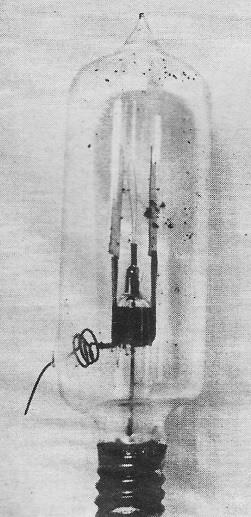
Fig. 1 - The "Key West Audion" diode tube supplied to the U.S. Navy in the year 1906 for use in the receiver apparatus of Fig. 4. By Paul G. Watson, Cmdr., USNR (Ret.) Description of the early diodes and first triodes that were employed in equipment almost 60 years ago. It is generally agreed that when Dr. Lee deForest put the grid, or third element, into the electron tube he started a major new industry in this country. How did it come to pass? Let's take a look at some of the high points along the way. During the summer of 1900, while living in Chicago, Lee deForest was experimenting with his "responder" as a means of detecting (rectifying) incoming wireless signals. Working in his bedroom, lighted by a Welsbach mantle-type light, deForest noticed that the light dimmed when the spark coil was in operation. Thinking that the electrical impulses were responsible for this light fluctuation, experiments were carried on for a time until, as a final check, the spark coil and gap were placed in a closet and the wooden door closed. No further light fluctuation occurred and, after a little more investigation, sound waves and not electrical impulses were proved to be the cause.
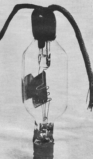
Fig. 2 - One of the first wire "grid Audions." This tube was made by McCandless in December 1906 for use by deForest at that time.
Fig. 3 - The second design for the "grid Audion" made for deForest. Note the seals on each end of the cylindrical envelope. While this start proved to be a false one, in deForest's mind was stamped the impression that, in some fashion, incandescent gases could be used to detect wireless signals. It was not until 1903 that deForest resumed his investigations of incandescent gases as a wireless detector. His laboratory was, at that time, at 11 Thames Street in New York City. It was here that he found that when two platinum plates were properly placed in the flame of a Bunsen burner, were shunted by a telephone receiver and a dry battery, and were connected to antenna and ground, signals from ships located in New York harbor were picked up. Realizing the impracticability of the flame detector, deForest then tried an electric arc which proved to be too noisy and was abandoned. In early 1905 deForest thought the incandescent gases from a hot lamp filament worth trying. He approached Henry Wallace McCandless, 67-69 Park Place, New York City, a manufacturer of miniature electric lamps, and asked him to make a small lamp with a carbon filament and containing it small platinum plate. He asked McCandless not to evacuate the lamp to a high degree as he felt the presence of some gas was necessary to get the desired result. DeForest connected this tube with the plate to the antenna and the filament to ground. A telephone receiver and a 22-volt battery, with the positive terminal to the plate, were connected from the plate to the grounded filament. Signals in fair strength, and quite a bit better than anything that had been previously tried, were heard. Diode Audions During the years with which we are here concerned, Lee deForest had been developing his own wireless system. He had interested the U.S. Navy and in 1904 and 1905 installed high-powered stations at Key West; San Juan, P.R.; Guantanamo, Cuba; Pensacola; and Colon, Panama. All were 26-kw. stations except for Pensacola which was 10 kw. By the fall of 1906, the two-element tube which had been given the name of "Audion" by C. D. Babcock, deForest's assistant, had progressed to the point where a receiving set employing these diode Audions was installed at the Key West Naval Station. A photo of this receiver is shown in Fig. 4. In this picture are two Audion control boxes, one of which is opened, exposing the three tubes. The 22-volt "B" battery appears at the left of the picture. Fig. 1 is a photo of the type of tubes supplied with the Key West receiver and to the Brooklyn Navy Yard. By virtue of their initial use at the Key West station, these diodes were known as the "Key West Audions" - a name which stuck as long as they were in use. It was deForest's opinion that in using the diodes a considerable portion of the received signal energy was bypassed through the telephone receiver and battery, or through the tuning device if used, since they were connected directly to the plate and filament which were, in turn, connected to antenna and ground. As an experiment, deForest wrapped tinfoil around one of these tubes, connected the antenna to the tinfoil instead of to the plate and noted a very considerable increase in received signal strength. DeForest then had McCandless make a tube with two plates, with the filament between the plates. The antenna was connected to one plate, the rest in the usual manner. This tube proved to be better than any other tried at that time. Enter the Grid McCandless made another tube for deForest. This time a perforated platinum plate was placed between the filament and the plate of the tube. The antenna was connected to the perforated plate and, when tried out, this tube exceeded all others in performance. In the design of this first three-element tube with a conventional element arrangement (as we now think of it), deForest apparently, in perforating this third element, was attempting to avoid completely screening the plate from the filament. Earlier experimenters with the Edison effect lamps had found that the "flow of particles" from the filament to the plate could be stopped by inserting a plate of metal between them. So that the "screening effect" of the third element would he minimized, deForest made a folded metal grid in December 1906 (of the type shown in Fig. 2) and had McCandless include it in a tube. This tube with the wire "grid" performed best of all. Because of its construction, the third element from this time forth was known as the "grid." With the "grid Audion," as the three-element tube was known to distinguish it from the "Key West Audion" (a diode), we now have, for the first time, a conventional triode - the patents for which were among the most valuable ever issued. Although electron control of the tube by the grid was actually involved as a technical matter, it came later. The grid was originally inserted in the tube as an antenna-coupling device to eliminate the losses in the telephone receiver and batteries, shunted across the original diode tube.
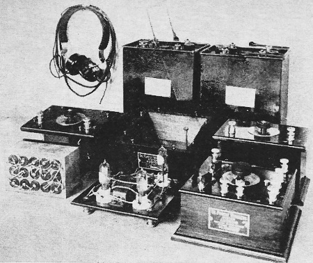
Fig. 4 - Receiving equipment set up at the Key West, Florida Naval Station in the fall or 1906, showing three "Key West Audions" (diodes) in the open detector box at the center.
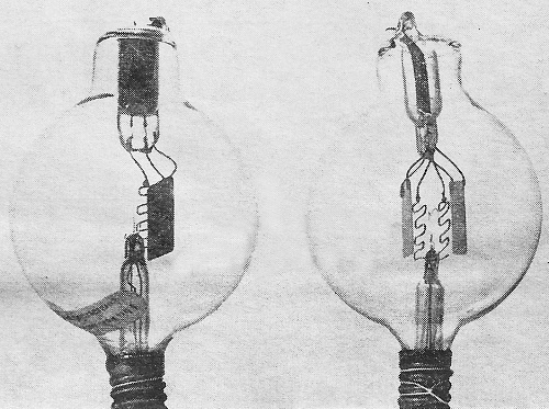
Fig. 5 - Tube at the right is a double-plate, double-grid Audion introduced around 1909. This tube, considered an improvement over single-grid Audion shown at left, was made until 1915. A second design of the "grid Audion," in which the improvements were hugely mechanical, was made by McCandless for deForest. This improved tube is shown in Fig. 3. A double-seal construction was adopted with the cylindrical envelope. The filament entered one end of the tube and connected to a candelabra screw lamp base, while the plate and grid entered the opposite end. For the first time a green covering was used to identify the grid lead while a red covering was used for the plate lead. A number of these tubes were made and tested in many ways. A. very few of these tubes still exist in the hands of collectors and museums and are the earliest triode tubes. Improvements in the Audion H. W. McCandless and his shop superintendent, Jacob C. Grogan, contributed much to the success of the Audion. It was their suggestions which, when carried out, increased the physical strength of the tube and added the double filament - before the end of 1906. They also suggested tantalum and tungsten as substitutes for the carbon filament. McCandless suggested, in the early part of 1907, that a spherical glass envelope should be substituted for the cylindrical one used up to that time, in order to reduce his manufacturing problems. This idea was adopted by deForest and the single grid-plate type shown at the left in Fig. 5 became the production model from 1907 to 1909. Many of these tubes were made and sold to amateurs and experimenters. In 1909, or the early part of 1910, deForest found that adding a second plate and a second grid to his Audion (right in Fig. 5) increased sensitivity and efficiency. There is, among some people, the idea that this second plate and grid were added to increase the tube's efficiency and capacity as an audio amplifier. In a letter to the author in 1952, deForest stated that this was not the case, that there was a gain in all applications - as detector and oscillator, as well as an amplifier. Better use was made of the filament emission, resulting in better tube action. The years of bitter patent strife; the development of the "singer" tubes, oscillators, amplifiers, regeneration, and many features all followed the developments described here and involved in some form, the "grid Audion" tube. Patent restrictions held tube development back until the Government's need for tubes in World War I brought matters to a head. After the war, with the formation of Radio Corporation of America, there was sufficient patent pooling to make tube manufacture possible. From that time on, the electronic tube industry grew by leaps and bounds.
Posted August 29, 2022 |
|||||