Radio Amateur Course - Resistance, Inductance, and Capacity
|
|
As mentioned many times in the past, some things never change regarding the basics of electricity and electronics. Resistance, inductance, and capacitance (termed "capacity" here) are examples and are addressed in this last of a three-part series which appeared in 1935 issues of Short Wave Craft magazine. When first starting out in this science, an effective introduction to the fundamentals can often determine whether a person sticks with it or finds another area of interest to pursue as a hobby and/or vocation. Analogous examples of voltage and water pressure, resistance and the diameter of a water hose, inertia in a spinning mass opposing a change in rate and an inductor opposing a change in current, etc., are presented along with some good sketches of the principles. See Part 1, Part 2, and Part 3 Radio Amateur Course No. 3 - Resistance, Inductance, and Capacity This is the third lesson in our Amateur Radio Course and it will deal with resistance, capacity, and inductance, as concerned with radio circuits. In order to understand how a vacuum tube oscillates, how tuned circuits work, and the function of a tuning condenser, it is necessary to become familiar with these three very important subjects. Resistance
In Fig. 1 we have a diagram showing how the size of a pipe governs the amount of water that can be forced through it. In Fig. 2 we have resistors connected in series. In Fig. 3 they are connected in parallel; the formulae are given in the text. Fig. 4 is the hydraulic analogy for the action of a condenser when alternating current is applied to it. Fig. 5 shows the magnetic fields and direction of current flow in straight wires and coils; also the right-hand rule is given, where, if the thumb points in the direction of the current flow, the four fingers will curve around the conductor in the direction of the magnetic field. When electrical current flows through a wire or some other conducting medium it encounters resistance or opposition, the same as the flow of material substances. For instance, a certain amount of water can be forced through a length of one-inch pipe with a definite pressure. In other words, the size of the pipe offers resistance to the flow. The larger the pipe becomes, the greater the amount of water can be forced through it at a definite pressure, or the larger the pipe becomes, the less its resistance would be. This holds true in conductance of electricity inasmuch as a fine wire or conductor offers a greater amount of resistance than a heavy conductor. The resistance of a conductor is inversely proportional to its cross sectional area and with some materials, in fact most of them, the resistance also increases as the temperature rises. In dealing with resistance in electrical circuits, we have what is known as Ohm's Law. In Ohm's Law, we have to consider three things: First, the flow of electricity, which is current; second, the force or pressure, which is voltage; and third, the resistance which the flow of electricity encounters. Three letters are assigned to the above, and they are: I = Current E = Voltage (EMF) R = Resistance The formulas for finding the resistance, voltage, or current, where either two of the three are known are as follows: I = E/R R = E/I E = R x I When two or more resistors are connected in series the total value of the resistance is the sum of all the resistors. In other words, three 5-ohm re-sistors in series would have a total resistance of 15 ohms. However, when resistors are connected in parallel the method of calculation is a bit more complicated. For instance, if we have three resistors connected in parallel, one has the resistance of 5 ohms, another of 10, and another of 20. The formula for expressing this is:
Capacity
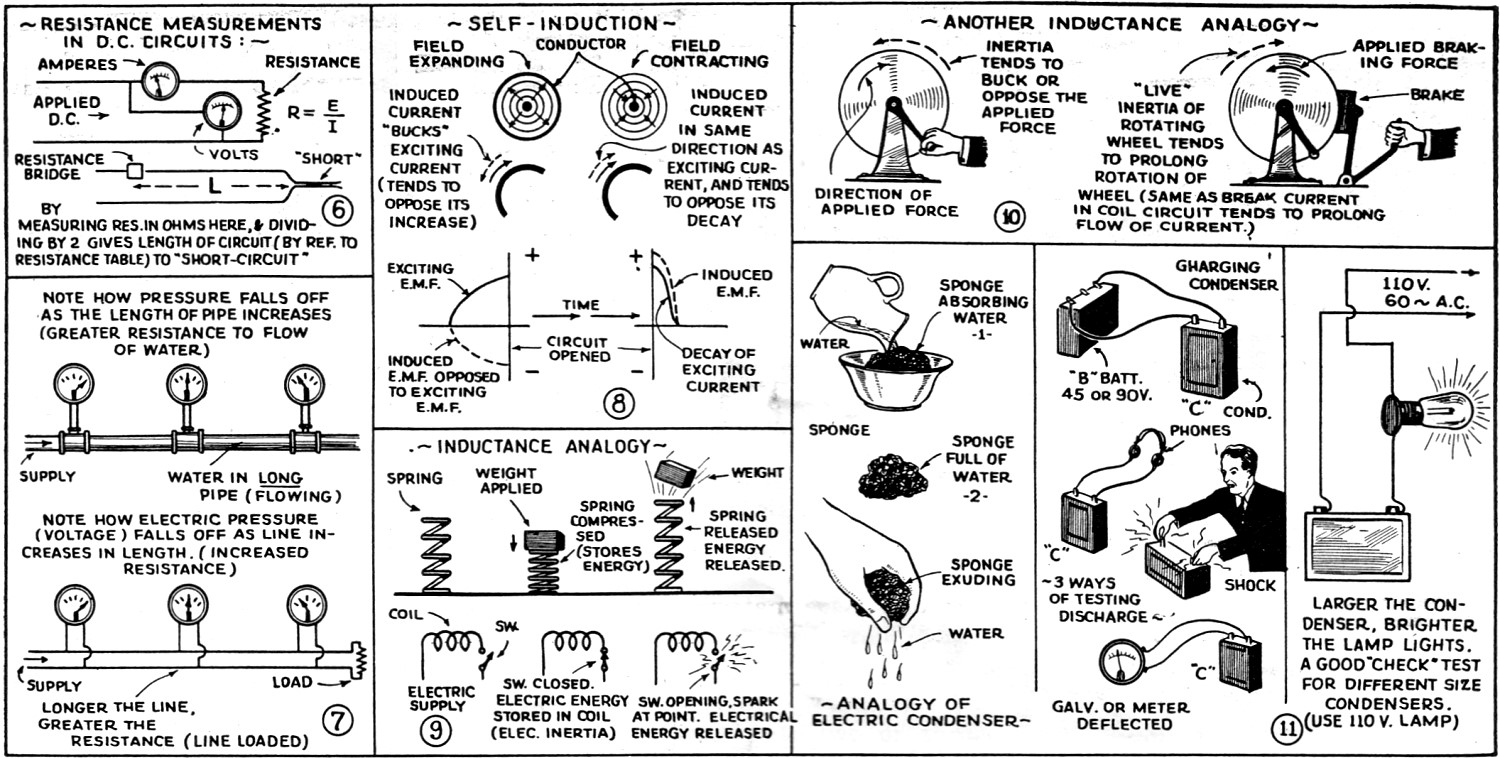
Fig. 6 above shows measurement of resistance. Fig. 7 shows how pressure or voltage decreases with increase in resistance to flow of water or electric current. Fig. 8 shows action of expanding and contracting magnetic fields. Fig. 9 shows mechanical "spring" analogy for inductance; Fig. 10 - Fly-wheel analogy of inductance. Fig. 11 - Analogies for condenser. Most of us are familiar with the now well-known condenser which is an instrument capable of storing up a certain amount of electricity and consists of two or more plates placed adjacent to each other, with insulation of either air or some other insulating medium. When a constant direct voltage is applied between the plates of a condenser, current will flow into the condenser, until the condenser becomes charged to its maximum capacity. The current then ceases to flow and the condenser is charged. Then, after the source of electricity (battery for example) is removed from the circuit, the condenser will hold its charge until, due to its inherent (conductivity of dielectric) resistance, the power is dissipated. If the insulation is mica or parafined (waxed) paper, the condenser will hold its charge for a considerable length of time. In large condensers of one or two microfarads the charge may remain in the condenser for several hours. This can be proved by short-circuiting the two terminals of the condenser and noting the spark, or an ammeter could be connected across the condenser and it would indicate the current flowing until the condenser was completely discharged and the power dissipated. The unit of capacity is a farad; however, in radio work, we use considerably smaller units in our condensers. A microfarad is one millionth of a farad, and one micro-micro-farad is one millionth of a microfarad. The most important part of a condenser is the dielectric or insulating material because, contrary to popular belief, it is in the dielectric that the charge resides. When a condenser is charged, the dielectric opposes the setting up of an electric displacement of an electric field in the dielectric and the charge is said to be the energy of the charging source stored up as electro-static energy in the dielectric. A simple analogy for the action of an electrical condenser is a sponge, which absorbs water when placed in a cupful of it, for example, and afterwards if pressure is exerted on the sponge, then it gives up the water stored in it. It requires 1 coulomb (ampere-second) to charge a condenser of 1 farad to a potential of 1 volt. A condenser having a capacity of 1 mf. (1 mf. = 1 millionth of 1 farad) requires a charge of 1 millionth of 1 coulomb to charge it to a potential of 1 volt. Inductance The coils used in radio circuits are called inductances or inductors. In the drawings we see how an electro-magnetic field may be produced around the wire when a current is passed through it. If the flow of current through a conductor is constant (D.C.) a steady electro-magnetic field is produced around the conductor. However, when alternating current (abbreviated A.C.) flows through a conductor, the current flow is constantly changing and likewise the field is changing. When current begins to flow through a wire the circular electro-magnetic field originates at the center of the conductor and travels outwardly away from this center in constantly increas-ing diameters and of course, extends into the space surrounding the wire. Until this field becomes of larger diameter than the wire, it causes a second current to flow in opposition to the main current. When the current flow through the wire decreases or stops, the circular fields collapse and are then said to cut the wire in ever-diminishing diameters. This induces a current in the opposite direction to the field but in the same direction as the original (exciting) applied current, tending to prolong the flow of the exciting current. This property of a coil or conductor to act upon itself or another inductor in close proximity to it, is called inductance. The unit of inductance is the henry and in most formulas it is usually designated by the symbol "L." A henry is the inductance of a circuit in which the induced E.M.F. is one volt; when the (varying) current travels at the rate of one ampere in one second. Usually in radio circuits, inductance values are indicated as one thousandth of a henry or - one milli-henry; a millionth of a henry is known as a micro-henry. The physical dimensions and form of a circuit, determine the amount of inductance and it is for this reason that our radio circuits consist of coils rather than straight wire, because a greater amount of inductance can be obtained by coiling the wire, also allowing considerably less D.C. resistance because less wire is used. A straight wire, of course, would have less inductance than one of the same length which was coiled. Induction subdivides into two branches - self and mutual induction. If the current passing through a coil, for example, is rising from zero to maximum value, such as when the circuit is closed from a battery, (or the first half of an alternation of an alternating current) the magnetic field around the wire is expanding and while this is taking place there is induced in the conductor a counter-current (and counter e.m.f. or voltage) which tends to buck or oppose the current (and voltage) which is producing the field. As one of the diagrams shows there is electrical energy stored up in an inductive circuit, just as if you had compressed a spring. The opening of the circuit, and spark at the switch, corresponds to releasing the compressed spring and heaving off the weight. Another analogy is the flywheel. The inertia of the wheel opposes any force to set it in motion; once in motion, the energy tied up in the wheel tends to keep it going, if any effort is made to stop it. Let us consider for a moment now the next phase of the action taking place when the circuit is opened or when the second half of the alternation of an applied A.C. is taking place. Now the magnetic field around the wire or turns of wire comprising the coil is contracting and while this occurs, the lines of magnetic force are cutting the wire in the opposite direction and a current of opposite sign is induced in the wire, this current being in the same direction as the applied (exciting) current which is flowing around the wire and creating the magnetic field. In other words, the self-induced e.m.f. is in the opposite direction, while the field is expanding about the wire, and tends to oppose it while the opposite is the case when the field is contracting and the current is then in the same direction or aids the inducing current and acts to prevent its decay. It will be apparent, of course, that while the current is varying in strength or let us say increasing, the field about the coil is expanding, and the lines of magnetic force expanding out from the coil composed of a number of turns, will induce a current by induction in a second coil, placed near or adjacent to the first or exciting coil. If we term the exciting coil No. 1, and the adjacent unconnected coil as No. 2, coil 2 is said to have a current induced in it by electro-magnetic induction. As the magnetic field in coil No. 1 subsides, the magnetic lines of force surrounding coil No.2 also subsides. At the same time these lines of force cut across the turns in coil No. 1 and induce therein an e.m.f. or voltage (also a current) and thus we have a third e.m.f. set up by induction. To begin with, we have the original exciting e.m.f. in coil 1; secondly we find an induced e.m.f. in coil 2; and thirdly, there is a reeinducedde.m.fe.m.fe.m.f. in coil 1, due to the reaction of the magnetic field surrounding coil 2, and this effect is what is known as mutual induction. The usual radio tuned circuit consists of a coil and a condenser, namely: inductance and capacity. Coils or inductances have what is known as inductive reactance, while condensers have capacity reactance. When the capacity reactance minus the inductive reactance equals zero, at some certain frequency, the circuit is said to be in resonance. When the condition known as Resonance has been established in any given circuit whether a series or parallel type circuit: then we know that the inductive and capacitive reactance are equal, and that they balance each other. When this condition has been achieved their reactive effect upon the circuit is zero. Under these conditions, or when the circuit has been made resonant, (by the proper adjustment of the capacity and the inductance of the circuit) any current flowing in the circuit due to an applied e.m.f. will be that due simply to the ohmic or direct current resistance in the circuit. Expressed another way, the current passing through such a resonant circuit will be given by the expression: I = E/R. The difference between the capacitive and inductive reactance of a circuit at some frequency is called the impedance. However, at resonance, this is always zero, and the losses in the circuit are due only to the usual D.C. resistance of the circuit, through which the currents are flowing. In Fig. 4 we see a hydraulic analogy of current flowing into a condenser. When the piston is moved forward, the elastic partition will bend or become curved but will not allow the liquid to be transferred from one side to the other. In the fourth lesson of our Amateur Radio Course, which will appear in the following issue of Short Wave Craft, the action and principles involved in Regeneration and Oscillating Vacuum Tube circuits will be discussed. Don't miss the next installment.
Posted December 10, 2020 |
|