U.H.F. Fringe Installations |
||
Multiple path transmission, diffraction around obstacles, absorption by foliage, and reflection from moving objects have always been challenges to the wireless system designer and/or user. Whether it concerns communications between a WiFi router and a notebook computer, a cellphone and a tower, an FM radio with a broadcast station, or deep space probe with an earth station, all of the aforementioned mechanisms must be dealt with to some degree. Although in a different way, even transmissions within a waveguide or coaxial cable deal with those same issues - reflections and the resulting standing waves have the same effect as multipath in terms of vectorially additive versions of the same original signal. Signal degradation issues can usually be overcome when all components are performing within specifications, by having knowledge potential causes, and then assessing the situation at hand. Of course an insufficient signal power from the transmitter, too-high Friis-determined atmospheric path loss, and inadequate receiver sensitivity under ideal conditions, will always result in an unresolvable problem. U.H.F. Fringe Installations
Television Consultant Radio & Television News Down-to-earth hints on how to squeeze every possible db of signal out of u. h. f. in the difficult fringe areas. After the first rash of new local u.h.f. installations, many service technicians find that additional customers are available, often in much greater numbers, in the u.h.f. fringe areas. This type of area differs from the familiar v.h.f. fringe area in many ways and requires a somewhat different approach and new service procedures.
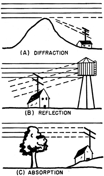
Fig. 1 - Some of the causes for weak u.h.f. reception. (A) Hills and obstructions do not diffract as much signal at u.h.f., as at v.h.f.; (B) reflections are more troublesome at u.h.f., especially from relatively small sized structures; (C) trees and foliage absorb signal energy at u.h.f. leaving less for the antenna and set. See discussion in text.
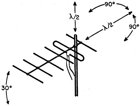
Fig. 2 - Directions in which an antenna should be tested before the installation is definitely made for u.h.f. receiver.
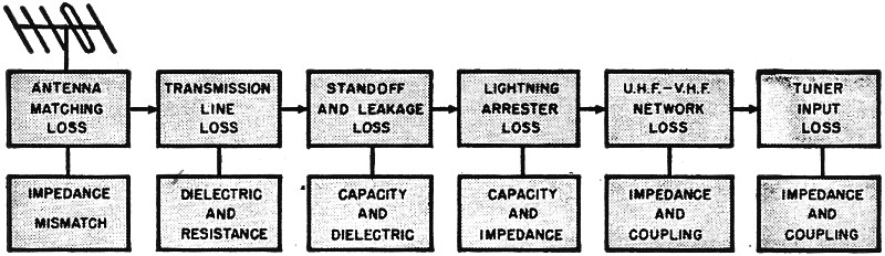
Fig. 3 - Various steps between the antenna and set in a typical installation showing the major sources of signal loss and their causes in each section. Fig. 1 illustrates some of the causes of weak u.h.f. signals and although they are also present in v.h.f. fringe areas, their effects are much more marked in the u.h.f. TV band. This article describes the various factors in a typical u.h.f. fringe installation which can be adjusted for better reception. When the signal at the receiver is so weak that "snow" appears, every change which will improve the signal strength is worthwhile. Getting every possible db of signal requires careful consideration of all the factors which can cause losses and the major portion of this article is devoted to pointing out these "signal sinks" and methods of avoiding them. Starting at the antenna we shall show how each portion of the installation can be designed for minimum loss and optimum signal. Antenna Installation The popular argument as to which antenna is best will probably never be settled, but for practical reasons, gain and directivity are the most important characteristics in the fringe area. Bandwidth, cost, and ease of installation are certainly secondary when a single station is received weakly and the acquisition of a new customer is at stake. For the typical fringe installation, therefore, a yagi antenna as in Fig. 2, a corner reflector, or a rhombic is recommended. Above all, when using a yagi, be sure that the antenna is cut for the channel to be received. In planning the installation it is well to remember that, optimizing all other factors, the actual signal which the antenna picks up represents the best possible reception. Therefore the type of antenna, location, mounting, and orientation can be considered as at least 50% of the job. This should be pointed out to the customer and the resulting installation charges can be based on the signal strength with which the technician must work. Recent advertising stresses the fact that some antennas use gold or some other type of plating, special dielectric spacers, or air dielectric to operate well in the u.h.f. fringe area. The boon of gold or silver plating is somewhat dubious since the surface resistivity of the antenna elements is normally quite low compared to the characteristic impedance. However, such plating does help to prevent rusting and deterioration. Dielectric losses at the antenna terminals can be considerable, especially if the dielectric used has a tendency to absorb moisture. One limitation of most antenna terminal arrangements is that they do not keep dust and moisture out. In this respect, the antennas which require no dielectric spacers are preferable. Where a dielectric spacer is used, the antenna terminals can be weatherproofed with special tape. Polyethylene, polystyrene, or vinyl tape can be used, provided the tape is pressed tight to keep water and air out and is not used so profusely that its thickness results in impedance mismatch. No more than two layers should normally be used and never, but never, use electrical friction tape or any kind of cellophane or paper-based tape. Having made a good connection, preferably soldered without flux, we are now ready to hoist the antenna into place for a trial orientation. Fig. 2 shows a simple six-element yagi and the direction of rotation and motion for optimum performance. Because of the appearance of so-called "space nodes," the antenna should be moved up and down, forward and backward as well as rotated to point towards the station. The up and down motion should be done slowly and extended for at least half a wavelength or about one foot at the lowest u.h.f. channel. It will be found frequently that maximum and minimum signal locations exist both in the vertical and horizontal plane, spaced half a wavelength apart. For the same reason the forward and backward motion is recommended. In addition to all these maneuvers, it is often helpful to vary the angle between the antenna beam and the mast, indicated by the 30 degree tilting at the left of Fig. 2. It may be necessary to repeat this procedure for several locations until the strongest signal is obtained. Since foliage absorbs u.h.f. waves to a great extent, be sure during the winter season that the antenna will not be blocked by trees or brush when spring comes along. Once the best location and directional position have been determined, the installation is made permanent. In addition to the normal rigidity and sturdiness required for v.h.f. antennas, the u.h.f. fringe installation must be guyed sufficiently to prevent swaying in the wind. A wind displacement of one foot, while tolerable at v.h.f. will often cause "picture breathing" or excessive fading on u.h.f. channels. On one u.h.f. fringe installation, good pictures were obtained at the time of installation, but when the customer's husband came home the picture fluttered until dinner time. Then a stable picture was obtained again. When the service technician came the next day, the fluttering was gone. In the late afternoon fluttering occurred again until dinner time. The cause for this vanishing flutter was apparently the reflections coming from a nearby highway where traffic was only substantial during the morning and evening rush hours. The reflection from passing automobiles was alternately in phase and out of phase with the main signal, causing flutter. Unfortunately there was no practical solution possible since the location of the home and the u.h.f. station required that the antenna be oriented towards the highway. Transmission Lines The flat 300-ohm twin-lead used for v.h.f. installations is quite lossy at u.h.f. and should never be used in weak signal areas. The author measured as much as 10 db loss at 800 mc. in a 50 foot length of flat twin-lead. By comparison, it was found that the same length of tubular twin-lead had less than 2 db loss. There are many different kinds of low-loss u.h.f. transmission line on the market and most of them are quite good. Open-wire line is theoretically the least lossy and. therefore most suitable for fringe installations. In actual practice, however, the open-wire line has some distinct drawbacks. Near industrial centers the air pollution is often quite bad and causes soot and grease deposits on the dielectric spacers. After a while the sum total of many coated spacers is sufficient to change the characteristic impedance of the line, resulting in standing wave and dissipation losses in the transmission line. Completely covered twin-leads do not suffer so much from dust and dirt because the insulation always keeps the grime away from the conductors themselves. More lossy than the transmission line itself are some of the indispensable accessories such as the standoffs, v.h.f.-u.h.f. couplers, and lightning arresters. The latter, especially, can be quite a trap for u.h.f. signals. There are basically two types of arresters on the market, one using resistive elements, the other using condensers. For u.h.f. the resistive models are not recommended since they cause not only a poor impedance match, but also unbalance the line. Some of the older style v.h.f. lightning arresters are unsuitable because their capacities are too large and, in many instances, the plastic case material has such poor dielectric qualities in the u.h.f.-TV band that impedance mismatch is considerable. The author checked the v.s.w.r. of several lines with lightning arresters and found those using "v.h.f. only" models have more than a 2.5:1 standing wave ratio. The latest u.h.f. or v.h.f.-u.h.f. models introduce less than 1.5:1 v.s.w.r. Thus, the selection of a good lightning arrester is another important factor in squeezing every db of gain out of the antenna in a fringe area. When a u.h.f. fringe installation also requires a v.h.f. antenna, care should be taken about using a v.h.f.-u.h.f. antenna coupler. All of the commercially available crossover networks have some insertion loss at u.h.f. In a fringe area, every db of signal strength is important. The best solution for fringe locations where both u.h.f. and v.h.f. antennas are needed is to run separate transmission lines to a suitable low-loss switch at the receiver. In many instances it is possible to simply connect each transmission line to its respective tuner input and depend on the u.h.f. converter or tuner to select the desired signal. Transmission line standoffs and supports are another potential signal trap. This is especially true in most fringe installations where the transmission line is quite long and is supported in many spots. The ideal standoff, or at least the best possible, is the type consisting entirely of polystyrene or some other low-loss dielectric. For rigidity, however, as well as for mounting purposes, steel is usually required. The most popular types of standoffs use a metal loop with a polyethylene grommet inside which supports the transmission line. At u.h.f., the metal loop together with the dielectric forms a condenser which effectively shunts the two wires of the transmission line. This capacity is quite small and by itself has little effect on the transmission line characteristic. When a great number of standoffs is used, however, their total capacity may seriously upset the impedance of the line. This is especially true when the standoffs are placed at equal distances resembling multiples of 1/2 wavelength at the channel being received. In this event considerable losses, as much as 6 db for 12 standoffs, can be encountered. For u.h.f. fringe installations, therefore, it is recommended that as few standoffs as possible be used while still maintaining good mechanical support for the line and, whenever possible, use standoffs without metal rings. Where a large number of standoffs is essential, try to space them at different distances from each other to avoid multiple 1/2 wave spacing effects. Needless to say, such poor v.h.f. practices as simply laying the transmission line on top of a metal roof, dropping sections into gutters, or taping it to metal supports are even more detrimental at u.h.f. All the measures discussed so far are aimed at avoiding signal losses, but there is one important step, the addition of a booster amplifier, that can actually increase the signal amplitude. U.H.F. Boosters In v.h.f. fringe installations the use of a booster is now almost standard practice and many different boosters are available. However, such u.h.f.-r.f. amplifiers are complex and u.h.f. boosters are still somewhat of a problem. The limiting factor in any booster is its noise figure as compared to the noise figure of the receiver. If the u.h.f. tuner or converter has a noise figure of 12 db at the channel used and the booster has a 16 db noise figure, then the addition of the booster will actually result in a snowier picture. Most continuous tuners have a noise figure of 14 db at optimized channels, and 24 db at poorly tracked channels. Turret tuners have a noise figure of 12 db at optimized channels, and 18 db at average alignment. Converter strips for turret tuners result in a 16 to 24 db noise figure with little chance of optimizing at any channel. Most u.h.f. boosters have a noise figure of 11 to 15 db, with a gain of 7 to 13 db. We can see from this data that the greatest advantage of the booster is an increase in gain. In other words, where the over-all receiver gain is low, a booster will help. Where it is possible to get a snowy picture with plenty of contrast, the over-all gain is sufficient and only a better noise figure can improve reception. In many cases for both continuous and turret-type tuners or converters it is possible to optimize at least one channel so that the noise figure is about as good as that of a booster. The real utility of the booster comes with the use of u.h.f. conversion strips in v.h.f. tuners. In these cases, the noise figure of the booster is superior and the over-all gain of the receiver is usually sufficient, so that the booster can really improve reception. In addition to the currently available u.h.f. boosters, new models will soon appear having noise figures below 8 db and stage gains of 10 and 12 db. This will be possible by the development of inexpensive u.h.f.-r.f. amplifiers. Improved versions of the 6AF4 and 6AJ4 are now in pilot production at RCA and G-E and these tubes will operate satisfactorily over the u.h.f. band, in grounded-grid circuits, and in regular 7-pin miniature sockets. These tubes will, of course, be used in most new v.h.f.-u.h.f.. tuners, but their application in u.h.f. boosters will help overcome the limitations of many older u.h.f. converters and tuners. Optimizing the Receiver The final destination of the u.h.f. signal is the input circuit of the TV receiver and at that point further improvements can be made to get the best possible picture from a weak u.h.f. signal. First of all, the various approved and time tested v.h.f. fringe receiver modifications should be tried. These include reducing a.g.c. bias, adding an a.g.c. delay circuit, realigning the i.f. section for a narrower response curve and similar measures. In receivers where double conversion is used, be sure the v.h.f. channel acting as first i.f. for the u.h.f. signal is tuned up for optimum response. It is possible to adjust v.h.f. input and mixer networks to less than 6 db noise figure if a cascode circuit is used and less than 9 db for a pentode r.f. amplifier. Checking the bandpass and over-all gain of the v.h.f. section will make the optimizing of the u.h.f. portion much easier. In many instances where an external converter is used, the output stage of the converter, usually a cascode, and the input of the v.h.f. tuner should also be aligned for best sensitivity and noise figure. The connecting cable should be as short as possible and its length should be trimmed for best picture. After all i.f. and v.h.f. adjustments have been checked, the u.h.f. networks can be tuned up. Most u.h.f. tuners and converters now in use are of the continuous-tuning type. Whether capacity tuned transmission lines, coaxially tuned lines, shorted rings, or other systems are employed, the problems of tracking the r.f. network with the mixer and oscillator networks and of impedance matching the input are always present. In continuously-tuned devices it is usually possible to get best tracking at the highest and lowest frequency and some sort of compromise at the center. For a typical u.h.f. fringe installation only one channel need be optimized and this makes the alignment process easier. Before adjusting anything it might be well to try different mixer crystals. Most tuners and converters use either a 1N72 or 1N82 in this circuit and performance of different crystals can vary considerably. Since the crystal usually is in a clip-type holder it is a simple matter to switch crystals, but it is also necessary to retune the mixer trimmer or touch up the r.f. bandpass network. The better equipped service technician can try improving crystal performance by putting a 1N21B crystal into the tuner. This is a more expensive crystal, usually used for government work, and requires a different mounting clip. Its performance is decidedly better than the 1N72 or 1N82. Again retuning is required. To align the r.f. network of most u.h.f. tuners and converters requires a u.h.f. sweep generator and oscilloscope and this operation can be performed in the shop, prior to the installation. Tune the main tuning control for the desired channel, then check the response curve, leaving the local u.h.f. oscillator on. The oscillator should produce a pip on the flat portion of the response curve, and the r.f. network is then tuned for the most even, narrow, and highest bandpass possible. To check the antenna input circuit, the u.h.f. sweep generator impedance should be 300 ohms and the coupling network should be adjusted for maximum response curve height. For detailed instructions on optimizing a turret tuner refer to the September, 1953, issue of Radio & Television News, which gives this data for the Standard Coil 82-channel tuner. The steps for adjusting the various circuits are the same as outlined previously, but the range of each adjustment is more limited since the turret tuning itself permits tracking for many more than the three usual spots. Many u.h.f. converters and tuners use hi-pass filters at the u.h.f. input and occasionally these filters are lossy or cause slight mismatch. Where adjustment is provided, try optimizing it, otherwise it may be possible to bring the u.h.f. antenna line directly to the r.f. network without going through the hi-pass filter. Another problem is the mismatch of the antenna line to the receiver input. Try cutting the transmission line 1/2 inch at a time until the best picture is obtained. Occasionally it is possible to improve picture performance by folding a 6 inch length of tinfoil over the transmission line near the receiver and sliding it up and down until the best picture is observed. Tape the tinfoil onto the line at the best spot. Fig. 3 shows the sum total of signal losses and the nature of each drop in signal. In order to get the best possible performance from a u.h.f. fringe installation it is essential that each of these losses be minimized or compensated. As an example, the antenna matching losses can be avoided by correct impedance match, i.e., using the right kind of antenna for the right type of transmission line. The losses due to the transmission line can often be overcome by the addition of a u.h.f. booster, provided that the noise figure of the booster is at least as good as that of the tuner. Standoff losses due to impedance mismatch can be minimized by using as few standoffs as consistent with mechanical support and avoiding the use of the type that uses a metal ring around the dielectric. The type of loss easiest to compensate occurs at the input to the u.h.f. tuner or converter. To avoid this loss it is essential for almost every fringe installation that the u.h.f. networks be realigned and tuned up for the weakest channel. This is especially important for continuously-tuned systems where mis-tracking can introduce losses of 10 db or more. In addition to tracking, the use of a selected crystal mixer diode is also recommended and the r.f. input circuit should be adjusted whenever possible. As a last step to insuring good u.h.f. reception, weatherproofing the entire outdoor portion of the installation is essential. Under weatherproofing we include the guying of the mast to avoid swaying and the resultant "picture breathing," as well as patching up each hole in the masonry or woodwork with weatherproofing material. The connection of the antenna to the transmission line should be weatherproofed as well as possible, with soldered connections wherever feasible. All tape used should be either polyethylene or vinyl and never should regular friction tape be employed. If the reader concludes after this article that a u.h.f. fringe installation is a complicated and time-consuming job, he is quite right. Competent service technicians know that such an installation requires a lot of time and equipment and therefore plan accordingly. As far as the customer is concerned, he should understand that because he lives in a u.h.f. fringe area the installation will cost him considerably more than it would in a strong signal location. Usually the entertainment value of TV in such remote areas is so great that set owners are quite willing to pay well in order to obtain television reception.
Posted March 26, 2020 |
||

 By Walter H. Buchsbaum