|
Television Forges Ahead March 1930 Radio News Article |
||
Some of the earliest television display schemes were mechanically scanned light projection systems rather than electronically raster scanned cathode ray tubes. This 1930 vintage article from Radio News magazine reports on a scheme developed by Arthur Watson whereby a specially formed rotating Monel* disk served as the rotating reflecting surface to produce the light scanning action. This invention was hailed as a breakthrough that would finally make commercial TV available to the masses. Mechanical televisions worked by transmitting scanned images of the original subject in the form of amplitude modulated electrical signals whose voltage was determined by the level of reflected light. A synchronizing signal was included in the transmitted data stream. The scan disk on the receiving end rotated at the same rate as the transmitter scanning disk, and an electric lamp's brightness was varied according to the signal's picture voltage level. As you might guess, the result was very crude, but it was a first step and did produce a useable televised image. Shortly thereafter, practical electronic scan systems were developed that eventually won out as the preferred television transmit/receive scheme. * Monel is a metal alloy of nickel and copper, used for dog tags in WWI and WWII. Television Forges Ahead
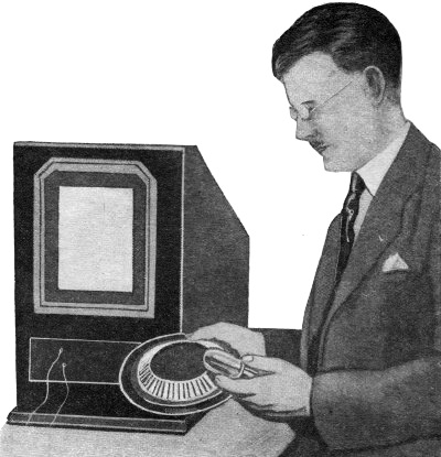
Photo © The Chicago Daily News Arthur H. Watson holding the new scanning disc which he invented and which may hasten the time when television will be available to everyone By Kenneth A. Hathaway Television development has been given new impetus by the invention of another type of scanning disc for use in receiving sets, the first account of which appeared recently in the Chicago Daily News. The new disc is one of the most flexible that thus far has been developed, in that it can be adapted to any known system of scanning that is in use at the present time in experimental work. It operates on the principle of reflecting light to the screen instead of projecting it through holes in the disc - a principle which in itself is not new, although the method by which the effect is obtained is original with the inventor, Arthur H. Watson, who heads the Watson Television Laboratories of Chicago. The design lends itself to manufacture with ease, since there are no adjustments to be made once the disc has been assembled. The reflecting surface is made of highly-polished Monel metal. Although several types of reflectors have been tried nothing better has been found. The metal was well known during the war when it was used to make unbreakable mirrors for the troops. As applied to the television disc, Monel metal has the property of retaining luster, and it can be bent to fairly sharp angles without injury. Reference to the illustrations will show that the segments of the disc protrude at an angle nearing that of ninety degrees. The complete disc is about seven inches in diameter, a qualification that permits the use of a comparatively small receiving unit. Aside from the screws that are used to hold the assembly together, the disc can be made of four parts: the Monel disc, and a base ring which carries the bearing, and to which is attached a ring molded in such a way that each of the segments on the metal disc will be given a definite angle. In order that the segments will be held rigidly in position a complementary ring is fastened to the base, and as it is clamped into position each of the segments takes the proper angle as determined from the experiments conducted in the laboratory.
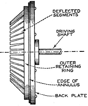
Cross-sectional view of the Watson television receiver, showing how the mirrors on the rotating scanning disc reflect light from the crator type neon lamp to the screen, which may be five by six inches square
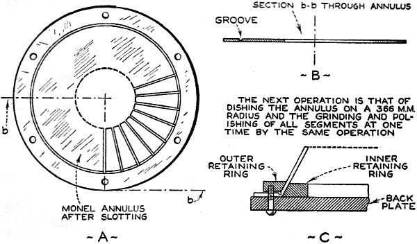
Details of the scanning disc, showing how the reflecting mirrors of highly polished Monel metal are bent to the proper angle The mounting of the disc is determined by the method used by the station transmitting the television impulses. Although attempts have been made to standardize the television branch of the radio industry, there seems to be no logical way in which the methods can be entirely standardized at the present time. Therefore, we find that different laboratories scan the image horizontally or vertically. In most of the methods the scanning line describes an arc, although the position of the arc differs. The ends of the segment may be at the top or the bottom. Regardless of the position, the Watson disc can be changed to conform to the transmitting system by merely varying the angle at which the disc is mounted. The size of the scanning element employed is seven inches in diameter overall and one and three-quarters inches in depth. The picture produced with this element, with the screen at a distance of fourteen inches, is as large in area as the scanning element itself, measuring approximately five by six inches. No lenses or optical reflection or refraction devices are used other than the segmental elements of the scanning device itself. An entire receiver may be housed within a cabinet nine inches wide, fifteen inches high and eighteen inches in length. Fig. 3 shows the scanning element, consisting of an annulus of Monel metal, and having inwardly extending radial slots separating the annulus at its inner periphery into as many segments as there shall be lines to the picture. This annulus is then cupped to a curvature on a radius of substantially 366 millimeters, and its concave face subjected to a single grinding and polishing operation, thus producing forty-eight perfect and identical optically correct focusing reflectors. Next, the segments are struck upwardly by die to an angle of substantially forty-five degrees from the axis of rotation, being the central axis of the annulus. The annulus thus prepared is mounted upon a Bakelite mounting disc, and by the use of a pair of complementary retaining rings the annulus is drawn tightly in engagement with the disc. Constantly changing inclination on the opposed surface of the retaining rings securely locks the segments to their proper adjusted and operable positions so that the optical axes of the segments diverge outwardly, each adjoining axis slightly higher or lower as the case may be. A lamp of the crator type is placed so that the image of its incandescent gaseous part is projected upon the screen S, and when the scanning annulus is rotated a succession of parallel lines traverses the screen. This system of scanning differs from any of the present known scanning systems, in that the exact shape and size of the spot traversing the screen is determined with great accuracy by the use of a mask associated with the lamp. Formerly a scanning spot of peculiar shape devised as most efficient could be obtained only through the use of a special die for stamping the holes in the spiral disc, which might be expected to result in difficulties arising through the wearing of the die, not to mention the high cost of the apparatus necessary for construction.
Salient Features of the Watson System Pictures five by six inches may be produced directly on the screen without any intervening means for the purpose of magnification. It may be instantly adapted to any type of television scanning systems in use today, an advantage not possessed by any other known system. No lenses or optical reflection or refraction devices are used other than the highly polished reflecting elements of the disc itself. An entire receiving machine may be housed within a cabinet nine inches wide, fifteen inches high and eighteen inches in length, and these proportions may be still further reduced if desired, The complete televisor comprises but four parts, the lamp, the drum, a motor for driving the drum and a screen. The problem of synchronization is taken care of in metropolitan areas by using a synchronous motor, and swinging the entire motor and drum along the axis of the drum to adjust for phase position between the poles of the motor, the major adjustment being carried out by momentarily breaking the motor circuit, permitting lag to take place. For intra-area reception a variable speed motor may be employed. During the months in which Mr. Watson has been developing his disc he has tried other types of reflecting material. Nickel-plating was one of the methods tried, but nickel-plating fails to hold its luster when exposed to the atmosphere and requires frequent polishing. The extensive use of chromium plating appeared to present another possibility, but it was discarded when it was found that imperfections in the metal would show through the plating in the form of pockmarks. The marks would not be apparent to the eye, but when the light was reflected upon the screen they were very much in evidence. Using chromium plating over a layer of nickel failed to serve the purpose, for the imperfections in the surface of the metal were made evident through the double plating. Accordingly, the inventor reverted to Monel metal, which reflects with nearly the same efficiency as silvered glass. At the same time the metal is lighter and more serviceable.
Posted May 27, 2022 Color and Monochrome (B&W) Television Articles
|
||