The Taylor "Super-Modulation" Principle (Part
2) |
||
Robert Taylor, along with inventing the concept of "super-modulation," also coined the new communications term "Intelligence Transmission Efficiency." It refers in part to the ratio of power in the intended sideband relative to power in the at least partially suppressed other sideband and carrier. Admittedly, I have not read this material enough to fully comprehend the concept of super-modulation, but at least based on the Fig. 1 waveform, there seems to be an element that adds a DC bias to the detected signal due to a nonsymmetrical (about 0 Vdc) transmitter modulation by pumping more power into the positive peaks. I'm happy to be corrected by any knowledgeable reader. For that matter, if you have experience with super-modulation and care to share it with RF Cafe visitors, I'll be glad to post your comments. See also "The Taylor 'Super-Modulation' Principle" Part 1 (Sep. 1948), Part 2 (Oct. 1948), "Understanding Super-Modulation" (Feb. 1950) Part 2. A discussion of a new system of modulation providing increased intelligence transmission efficiency.
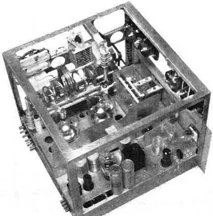
The Taylor Type 900-A transmitter with heat-dissipating top open to show details. By R. E. Taylor, Taylor Transmitters In pursuit of a means toward greater "Intelligence Transmission Efficiency" or ITE, with either orthodox or advanced methods, further inspection of the systems discussed so far, along with the action of the linear detector in receivers, shows some interesting features. As previously mentioned, conventional practice of necessarily having the sideband or talk power 6 db. or more below the carrier level, has been a great handicap to amateur and other forms of radio communications. Therefore, if there can be devised some method of bringing up the sideband or talk power level and of reducing or compressing the original carrier power interference level at the same time, we will have quite a reduction in interference and noise, with an increase in the power level and range of the intelligence to be transmitted and received. Past methods of transmitter modulation for sideband power have made this impossible. One of the reasons is the detector action in the receiver. Any attempt at greater than so-called 100 percent modulation for increased sideband power, or the reduction of the carrier level with respect to a given amount of audio supplied in the form of modulation, results in detector distortion. Thus, we have been limited to the sideband power 6 db. or more below the carrier interference level. Suppressed carrier transmission has been used commercially for quite some time along with single sideband. However, in reintroducing the carrier at the receiver, it has to be properly phased and within a few cycles of that of the transmitter, while the amplitude of the reintroduced carrier is also important where a low degree of distortion from the receiver detector is important. There is a reduction in noise level in single sideband however, characteristic of any really narrow band reception. However, heterodyne interference by the carrier from another AM transmitter with receiver carrier reintroduction is another matter to be considered. The one past exception for increased true sideband power is wideband FM in high frequency broadcast service where the permissible modulation index is high and the frequency swing is about 75 kc. each side of the instantaneous carrier frequency. Here, the carrier in some instances is almost all converted to true sideband power of a high ITE, as the power distribution of the modulation also affects the amplitude of the carrier frequency. However, when the modulation index and frequency swing is held down as in NBFM, the resulting sideband power is limited to about one half or less that of a standard AM signal. On long distance communications or where the signal is weak, it often sounds as though the percentage of modulation is low with a strong carrier. In cases of amateur BCI trouble, NBFM has been substituted for AM with a great loss of sideband power. For the fellow with a telegraph transmitter, it has been an easy way to get on phone. In approaching greater sideband power and reduced carrier interference levels, further tests of the 900-A transmitter previously described disclose some very unusual accomplishments. Sideband power has been increased 3 or 4 db. to about plus 48 db. in each sideband, while the carrier or interference level has been lowered by about 3 db. to an effective level of about plus 49 db. or about 1 or 2 db. difference in level of the separate functions. Now we find that by raising one level and lowering the other, we have almost overcome the 6 to 10 db. difference normally experienced, and effectively increased our "Intelligence Transmission Efficiency" by 6 or 10 db. from the transmitter-receiver standpoint. With past reasoning and methods as a basis for understanding, we bring to light a number of new principles heretofore unused, in permitting the above. Of the new principles involved, some have been previously mentioned. However the coordinated functioning of additional effects with controls, permits new thinking and advanced reasoning, opening many new fields as follows. The application of the positive modulation energy directly to the carrier output power, in the form of r.f. power triggered at an audio rate and controlled by the positive audio to be transmitted, adds to sideband power. By effectively dividing the positive and negative half cycles of audio for modulation, we can extend or limit their amplitudes and time linearly as desired. The effective separation of the r.f. carrier portions with respect to positive and negative modulation and time, so that each as divided may be classified as positive modulation carrier and negative modulation carrier, allows control of each as desired. The semi-suppression or compression of the carrier power, during positive modulation for sideband power, to a predetermined level quite some degree below that of the non-modulated carrier level, becomes possible. The transmission of the r.f. carrier negative cushion of predetermined amplitude and time for the negative modulation half cycle prevents distortion by negative peak clipping in the receiver detector. The audio a.c. component reference level or zero is elevated to a new increased operating position during positive modulation and high sideband power production. The carrier component is reduced during positive modulation to a low interference level, far below that of the non-modulated carrier power level. The successful use of separate tubes for carrier and sideband production, both independently controlled and contributing their power directly to the transmitter output as required is possible. Provision may be made for a crossover of sideband power and carrier power levels, with the sideband power far above, and the carrier power below the originating point levels. This permits correspondingly greater signal voltage out of the detector at reduced carrier level interference, due to the effective raising of the audio a.c. component and the reduction of the r.f. reference or zero levels in the receiver detector action.
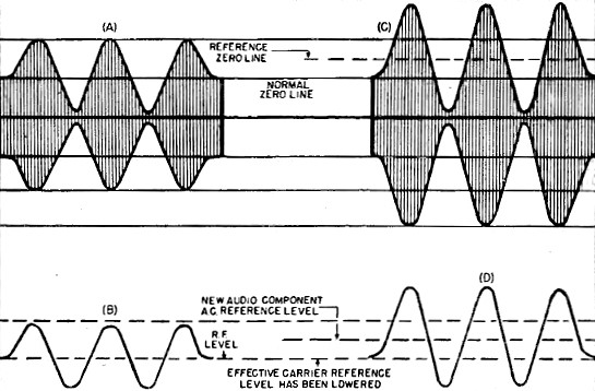
Fig. 1 - The effect of extending positive modulation peaks with carrier constant by increased or expanded audio a.c. reference level.
Modulation and r.f. section of the Type 900-A transmitter. A modulation effect in the receiver detector is apparent as a result of the changing reference levels and a.v.c. action, contributing somewhat to increased detector action efficiency. This brings about a corresponding reduction in the receiver bandwidth, noise level, and other effects common with any narrow-band reception. It has been known for some time that modulation greater than 100 percent can be used on positive peaks to great advantage if it is linear, provided the negative peaks do not clip or shut off the carrier. This effect does not appear as objectionable distortion in the output of the receiver detector, but appears as added signal intelligence output on the upward swing in the linear detector of the modern receiver. In Fig. 1, careful study of transmitter modulated output waveforms with both conventional and linearly extended positive peaks discloses some interesting conditions. Detector reproduction in both cases at B and D can be identical in waveform to that of the transmitter at A and C. However, in C considerably more sideband power is produced by the transmitter with greater signal strength out of the detector at D as compared to B. If we check for the center line or reference zero along the vertical lines between the tips of the positive and negative peaks at C, we find it effectively elevated by one half over the normal zero of A. Consequently, at the same time, by raising of the reference level, we have effectively reduced or caused the r.f. component reference level to be placed at a position lower in amplitude. This is duplicated in the detector action of the receiver. With this simple function as a working basis we determine that increase of the sideband power along with the decrease of the carrier or interference level is possible, if properly arranged. As mentioned, output of the two tubes PA and PM of the 900-A transmitter as to power delivery and timing control was the result of the divided audio out of the modulation transformer acting to trigger the positive and negative modulation for sideband power. We noted before, that during positive modulation by tube PM a certain amount of the unmodulated carrier power being delivered by tube PA was replaced by that from tube PM with a reduction in power required by tube PA, effectively amounting to the increase of PA's operating efficiency with respect to the power level as at no modulation. This reduction of the tube PA power output is of course caused by a proper and efficient reduction of the plate power input, which was the result of lowering the r.f. drive as mentioned and shown at DP2 of Fig. 3. Control of this function was the result of the r.f. voltage swing across the voltage dividing net of Cm and Cp, energized from the r.f. reservoir R. Having determined that tube PM can be put to work for the short time required, it was found that it could be made to do the majority of the work as far as providing power output during positive modulation, as well as to deliver power far greater than conventionally allowed. With this high power delivery function of tube PM, its power output is increased with the decrease of tube PA's power output from normal carrier level downward. PA's decrease is then simultaneously replaced by that from tube PM on the upward sweep, but with r.f. triggered at the audio rate of the r.f. excitation drive pulse to tube PM. We have then replaced, during positive modulation, some of the normal carrier power, with modulation energy in the form of triggered r.f. This turns up as sideband power produced by tube PM in addition to the non-modulated carrier. Then, during positive modulation, we have tube PM producing sideband power both above and below the non-modulated carrier level. The carrier, containing no intelligence, has been compressed or moved down to make room for the greater upsweep of the tube PM. Although it is an r.f. tube, PM contributes the r.f. at the audio rate of its r.f. drive. Of course during this compressed carrier period, the interference level at the receiver has been reduced by the almost total absence of carrier, with no receiver carrier reinsertion required. Now comes one of the unorthodox events; the return of the carrier to about full non-modulation level, or less if desired, for the function of the negative modulation half cycle, providing a cushion for the negative modulation peak, and preventing flattening or clipping by a so-called over modulation effect. This restored carrier cushion is for, and only during, negative modulation, with the amplitude and time of the restored carrier cushion subject to regulation. Functioning as the carrier cushion for negative modulation, for maintenance of the linearity during the over-All upward and downward sweep, the timing and amplitudes of both the negative peak and the carrier cushion depth can be adjusted to prevent over modulation on the negative half cycle of modulation. Carrier semi-suppression, which we shall hereafter refer to as carrier compression, then takes place during that time that the positive modulator is allowed to fill the compressed carrier valley with side band power energy. Effectively then, during transmission, the transmitted output power is just about all side band power with just a small amount of carrier sufficient for detector demodulation action. The reestablishment of the carrier during negative modulation as a cushion, which we shall hereafter refer to as the negative cushion, is not important with respect to the positive half cycle of modulation but is reintroduced only for the negative swing of the modulation or sideband power being received by the detector. As we are transmitting a very small amount of carrier during positive modulation, and a full negative carrier cushion during the negative modulation half cycle, we find that a second separation of effective actions is possible. In conventional use, where the carrier is present in full for both the separate functions of positive and negative modulation, we can however, divide it with respect to time, so that we have carrier presence for positive modulation, and carrier presence for negative modulation. To go a bit farther, we have what we can call positive modulation carrier and negative modulation carrier, with respect to the intelligence transmitted. Each is separate as to time and operation so they may be divided with respect to modulation function and sideband power production. Therefore, by transmitting separately the so-called negative carrier as used for the negative peak cushion, we have almost eliminated the transmission of the positive carrier. At this time, the output transmitted is about all sideband power, with the reinsertion of the negative carrier at a time where its average effective ratio as to heterodyne interference production at the receiver is far below that of the amplitude of the sidebands during positive modulation. Its filling in as the negative peak cushion in timing does not take any power away from the sidebands which are at maximum amplitude level during the positive modulation function.
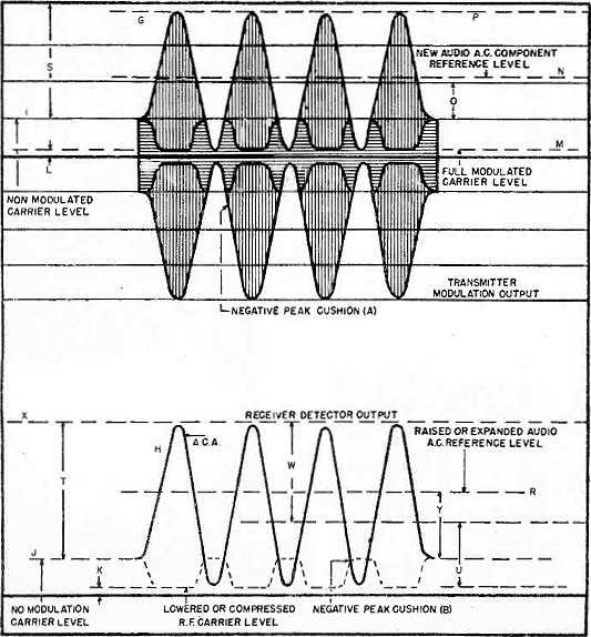
Fig. 2 - Transmitter and receiver waveforms obtained with "super-modulation." Fig. 2 at G shows the transmitter modulated envelope output above, with the detector signal output below at H. The positive modulation half cycle is considerably extended, the carrier compressed during positive modulation, and the negative peak cushion reintroduced for the negative half cycle of modulation. Of course, if the positive peaks are allowed to flatten out on top, the same will appear in the detector output as distortion, the same as negative peak clipping. Inspection of the patterns in Fig. 2 shows considerably more modulation or sideband power output from the transmitter as shown at S than that at O, normally available in standard practice. Detector reproduction at H is identical in linearity and waveform to the transmitter output. We now find that the audio a.c. component reference level, which we shall hereafter refer to as the "Audio Zero," has been raised along the vertical lines between the positive and negative peaks of the modulated envelope from that at I to that as shown at N. The same effect is reproduced in the detector action with the new audio zero raised from that at J up to R. As mentioned before, where we raise the audio zero, we have at the same time lowered the r.f. reference level with respect to the new audio zero. This will be the amount from that at N down to I or the reverse of that of the elevated audio zero. Now with the incorporating of carrier compression and negative peak cushion, we find that the carrier reference r.f. level can be even further separated from the audio zero, down to about that at M from that at I. At the same time this allows the compressed carrier valley from I to M to be filled in with audio triggered r.f. during positive modulation, from the positive modulator, for added sideband power output. With the new lowered r.f. component reference level reduced from J to K, during this period of transmitter carrier compression, the high sideband power appears in the detector output on the upward sweep, as increased output corresponding to that of the increase in the transmitter from the compressed level of the carrier. With the transmitter output at G, the side band power increase is observed, with the upward modulation far more than the usual two times carrier. We have also added extra sideband power, as shown below the non-modulated carrier level, during the carrier compression. Inasmuch as the instantaneous peak power output under modulation is the square of the increase which is conventionally 4 times or less, with the increase to P, our peak power can be considerably greater and reproduced as larger signal voltage out of the detector in the receiver as shown at H. The carrier interference level is reduced far, below the intelligence transmitted and received, instead of the reverse as in conventional practice. Therefore, if we listen to t he "super-modulated" signal from the detector as at H at usual volume, the receiver gain could be reduced so that the carrier level would drop by that amount between R and K or about equal to that between N and M at the transmitter output. The resulting receiver gain reduction, would effect about the same reduction of the interference level in the receiver. The reintroduced negative carrier cushion for the negative modulation half cycle as shown at A for the transmitter and the resulting detector action at B, functions only during that time required for the negative modulation, permitting the negative peak to be linear and efficiently reproduced at the receiver detector with low distortion. A 900-A transmitter, arranged for increased sideband power production with increased degrees of carrier compression as shown in the modulated envelope at Fig. 2, was adapted by rewiring the power amplifier and positive modulator output circuits with heavy copper bus to handle the terrific power peaks that would develop under expanded positive modulation and side band power. As shown in Fig. 3, we also arrange for the increased modulation amplitudes as Mp, greater carrier compression as at Na, and negative carrier cushion insertion at Nc, by the rearrangement of the voltage swings across the r.f. drive divider Cm and Cp, for the proper r.f. pulse drive power to tube PM. An increase in the r.f. power at reservoir R is necessary to maintain the new amplitude requirements of the larger r.f. trigger pulse at Rp. Tube PM will then provide an increase in the amplitude of the power output at Pp, which in turn is delivered to the output tank circuit as additional positive modulation energy resulting in Mp. This added modulation energy appears in the transmitter output as emphasized sidebands far greater than before. At the same time a larger degree of carrier compression appears at Nu for a separate but coordinated function, which is effected by further reduction of the power input and output of tube PA during this period.
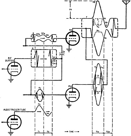
Fig. 3 - Expanded "super-modulation" showing waveforms at various circuit points.
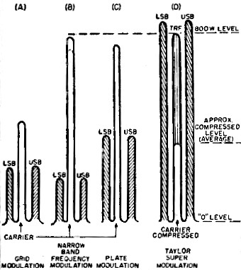
Fig. 4 - Panadaptor test comparing super-modulation" vs. other conventional systems. To take advantage of the power production facilities of tube PM as at Pp, we arrange for tube PA to rest, and dispense with most of its carrier at the same time. The accomplishment of this is very simple with this system with the operational functions previously used and extended to a greater degree. Where we reduced the r.f. drive power DP2 to tube PA by a small amount during the time that tube PM was allowed to work, we find that the input drive to PA can be further reduced, as long as its power output does not go below the power output pick-up generating capacity of PM. We want the output of PM to work upward above the uncompressed carrier level at F. In addition it must replace the compressed carrier at I (Fig. 2). With proper proportioning of the voltage across Cm and Cp so that PA is allowed to decrease in operation during positive modulation we must arrange to get it back into somewhat near full operation as at Nc. This must occur in time for the negative modulation half cycle Mn, to avoid distortion in the output by negative clipping. When tube PM has completed its positive half cycle it requires no r.f. drive at Rp. We take a portion of this drive and apply it to the tube PA, allowing PA to produce normal carrier again as at Nc or F, during the negative modulation peak. Functional timing in Fig. 3 will now be about as follows: before the one cycle modulation function starts as over time T1, T2, and T1a, T2a, the output of the audio trigger tube as well as the input and output of tube PM is almost zero. PA provides the carrier output at F, as the result of the r.f. drive at E. Over time T1, the positive audio pulse at Pa allows the r.f. pulse Rp to be applied to the input of PM from the source at R. The r.f. input to PA has been reduced at DP2, at the same time as the output tube PM is providing power output Pp. Power output from PA is at the level of Na which is filled in with C1 as part of Pp from PM. The balance of power at Pp provides the positive modulation shown at Mp. At the beginning of time T1a, compression Na starts to function downward toward its minimum level. At the same time C1 replaces the compression, simultaneous with positive power Pp effecting upward modulation Mp. At the mid-point of time T1a, this procedure is reversed so that at the beginning of time T2a, Pp and C1 are back to about zero with Na reestablished to about the level of F. This also, over T1 established DP3 at about the same level as at E during the two time intervals. Time T2 now follows. The negative audio half cycle Na allows the drive pulse DP1 of the r.f. drive power to be applied to tube PA with the function following the pattern of Na. Over time T2a, PA's output shows as Mn from Na downward to the mid-point of the time period, with the return to Nc level the same as F upon completion of this time period. Action during the T2a period by PM, is about zero as indicated, or the same as before the beginning of time T1 and T1a. During later tests, the expanded TSM system was pushed somewhat farther, to what seemed about the maximum capabilities of the tubes used in the 900-A transmitter at the time. The non-modulated carrier output was, in this case, about 800 watts represented by about 4 amps into approximately a 50 ohm load. The non modulated plate power input to the power amplifier tube was about 3000v. x 320 ma., or 960 watts. Power input to the positive modulator was 3000v. x 10 ma., or a total plate power input to the two tubes of 990 watts, for the carrier power output of 800 watts. This represents a plate efficiency of somewhere around 80 per-cent with respect to total input over output. With full heavy modulation at reduced bandwidth, power input to the power amplifier tube was reduced to about 150 watts or 3000v. at 50 ma. At a plate efficiency of about 75 percent this allowed a compressed carrier power output of about 100 watts. The positive modulator with plate voltage of 3000 volts was showing plate current peaks of 500 to 600 ma., so the maximum plate power input was computed to be about 1800 watts on the heavy modulation passages. Of the 1800 watts input to the positive modulator at the maximum modulation, an efficiency of about 90 per-cent allowed about 1600 watts of sideband power output with no spread or splatter. This was over and above the 100 watts of compressed carrier level. The r.m.s. measured output was found to be about 1700 watts with a load current increase of from 4 amps at no modulation carrier level up to about 6 amps into the load at full modulation. This represented an increase of 50 per-cent of the uncompressed carrier output for full modulation instead of the usual 22 1/2 per-cent. Of the 1600 watts of sideband power output, about 800 watts was in each sideband or a talk power level of plus 51 db., with terrific peak power, while the compressed carrier of about 100 watts was around plus 42 db. This allowed an effective 20 db. spread of increased intelligence transmission efficiency over the normal method. Fig. 4D shows the carrier and side bands of the modulation tests when viewed on a Panadaptor during some of the first tests. The Taylor "super modulated" transmitter output at no modulation was around the 800 watt mark, while with modulation as in this test, each of the sidebands exceeded the 800 watt level before any distortion appeared in the picture. Fig. 4A represents the carrier and sideband power of a 1 kw. input grid modulated transmitter. 4B represents that of a 1 kw. input NBFM transmitter where the modulation index and frequency swing is within the legal limits for amateur and communication service, and that of 4C a plate modulated 1 kw. transmitter with the carrier output a little less than for NBFM but with considerable more sideband power. 4D, as mentioned is the Taylor "super-modulated" transmitter at a kw. input according to the means of rating the other systems.
* The modulation system disclosed in this article carries a U. S. patent and foreign patent with other patents pending.
Posted May 19, 2020 |
||