Microwaves Part VI - Test Equipment & Frequency Conversion |
|
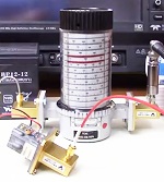
Resonant cavity wavemeter (YouTube) Part VI of C.W. Palmer's series on Microwaves discusses "equipment used for measuring frequency, and crystals for receiver frequency conversion." He spends a lot of time describing high frequency wavemeters - how they work and how they're used for measurements. I always thought there was something cool about the resonant cavity type wavemeters and am impressed that someone came up with the idea (click image to left for a video). When I first saw one I thought the cylinder rotated automatically to indicate the resonant frequency, but in fact your need to manually rotate the wavemeter's cylinder while monitoring a power meter. It's cool anyway, though. Note that in 1949 when these articles appeared in Radio−Electronics magazine, the word we nowadays write as "coaxial" was then hyphenated as "co−axial." Microwave Series -- Part 1: How Radio Waves Can Be Transmitted Inside Pieces of Pipe (4/49), Part II: An Introduction to Standing Waves, Cavity Resonators, and Representative Examples of u.h.f. Plumbing (5/49), Part III: Tubes for the Microwave Frequencies, Giving Special Notice to the Lighthouse Triode, Velocity-Modulated Tubes, and the Magnetron (6/49), Part IV: How Waveguides Are Joined and Tuned for Lowest Possible Loss (8/49), Part V: Special Sections of Waveguide Are Employed as Transformers (9/49), Part VI: Some Equipment Used for Measuring Frequency, and Crystals for Receiver Frequency Conversion (10/49), Part VII: Action of Below-Cutoff Attenuators and of TR and Anti-TR Switches (11/49), Part VIII: Receiving and transmitting antennas for microwave communication. Some equipment used for measuring frequency, and crystals for receiver frequency conversion.
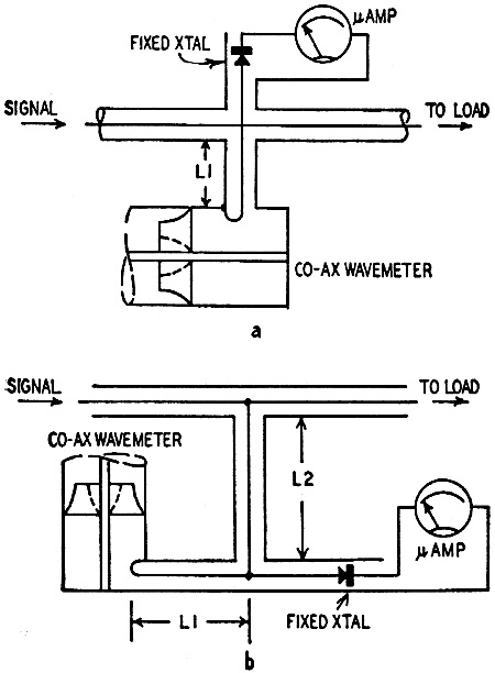
Fig. 1-a - Coaxial wavemeter for transmission or absorption use, Fig. 1-b - Absorption type. By C. W. Palmer Correct operation of microwave equipment depends on many factors, one of which is accurate frequency adjustment of transmitters and receivers. A slotted waveguide with a calibrated probe (Radio-Electronics, May, 1949, page 56) is probably the most common frequency-measuring device, but there are occasions when it is better to use a direct-reading wavemeter. Wavemeters for microwave work are of three general types: co-axial, cavity resonator, and transition. The first type consists of a section of co-axial line small enough that only (the Tm0,0,n) mode can function. Resonance is then found at odd quarter-wavelength points (1/4, 3/4, etc.). Wavelength is found by measuring between successive resonances with a centimeter scale, an extremely handy method in microwave setups. The instrument needs no calibration, of course. Loop coupling to the co-axial line is commonly used, with the loop located near a short-circuited end of the co-ax where it is always in a position of maximum magnetic field.
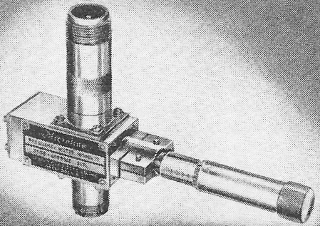
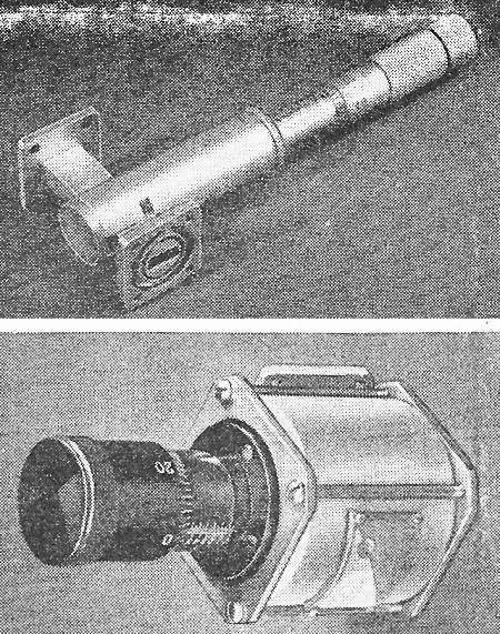
Fig. 2 - Photo of the coaxial wavemeter instrument of Fig. 1-b. Courtesy Sperry Gyroscope Co.
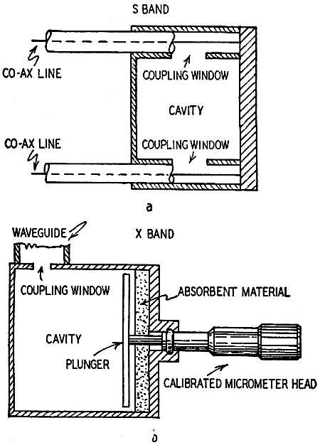
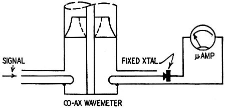
Fig. 3-a - A fixed-frequency cavity wavemeter. Fig. 3-b - A variable-frequency cavity meter. Resonance can also be obtained at even quarter-wavelength points (2/4, 4/4, etc.) if the line is short-circuited at both ends. Several types of co-axial wavemeters are shown in cross section in Fig. 1. A commercial unit is shown in Fig. 2. The cylindrical or cavity wavemeter has a distinct advantage over the co-axial type in that it has a much higher Q and, therefore, the points of resonance are more distinct and sharply defined. Its disadvantage is that it is not self-calibrating. In fixed-frequency cavities used as frequency standards it is desirable to use the lowest mode to avoid confusion resulting from other modes of operation. In adjustable wavemeter cavities with an adjustable plunger at one end, a higher mode having a zero surface current where the plunger and the sides of the cavity meet is necessary. When a higher mode is used, lower modes are attenuated or rejected with absorbing materials placed behind the plunger, with grooves filled with absorbing material and parallel to the surface currents on the end plate, by the method of coupling, and by damping wires. Cavity wavemeters have Q's that approach a theoretical limit of about 55,000. Actual measurements on existing units have shown Q's of better than 40,000. This means that with a good cavity wavemeter accuracies of ±28 kilocycles at a frequency of 3,000 megacycles are possible. Fig. 3 shows two types of cavity wavemeters. The third type or transition wavemeter may be thought of as half co-axial line and half cylindrical cavity - hence its name. It is a cylindrical cavity along whose axis projects a piston which has a diameter considerably smaller than that of the cavity. The diameter of the cavity is large enough to support the the Tm0,1,1) mode. The dimensions of both the plunger and the cavity control the frequency. Thus it is necessary to calibrate this type of wavemeter. All three types described can be calibrated as direct-reading devices. Connecting Wavemeters A wavemeter is called a transmission instrument if it is used in the main line, and a reaction or absorption instrument if it is in a side arm of the waveguide or transmission line. A transmission wavemeter in use is shown in Fig. 4. It is couples to a co-axial line with coupling loops projecting into the wavemeter cavity. A crystal detector and d.c. microammeter complete the indicating circuit. Two reaction wavemeter circuits are shown in Fig. 5. At a the distance L1 is such that the side arm presents a high impedance at the junction to the main guide when the wavemeter is off resonance. At resonance the impedance drops so that less power reaches the crystal and meter. At b the same action takes place, except that the indicator crystal and meter are placed in the branch circuit at a point of normally high impedance. Length L2 is independent of L1, which is adjusted to present a high impedance at off-resonant frequencies. Fig 6. shows two examples of commercially available wavemeters. One is the transmission type for a frequency range of 22,950 to 24,950 mc. Second is an absorption-type wavemeter for a frequency range of 8,500 to 9,400 mc.
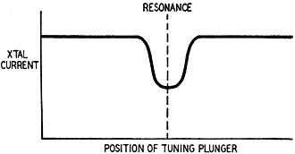
Fig. 4 - Coaxial transmission-type wavemeter. In all the absorption-type wavemeters the current in the crystal varies as shown in Fig. 7. If the coupling is too tight, this curve becomes distorted and it becomes necessary to reduce the size of the loop or rotate it so that it cuts fewer lines of force. The accuracy of a wavemeter depends on the "loaded Q" and the size of the scale. For example if an accuracy of ±0.001 cm is desired, the scale must be fine enough to read to three decimal places and the resolution (sharpness of tuning) great enough to indicate a wavelength deviation of 0.001 cm. In other words, the frequency-response curve of the wavemeter must drop to its "half-power" points on each side of resonance in a space of not more than 0.001 cm.
Fig. 5 - Two reaction-type wave meter circuits.
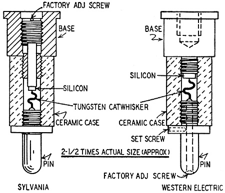
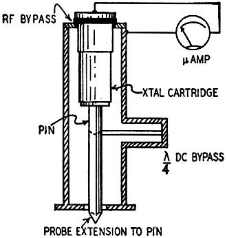
Fig. 6 - Transmission and reaction wavemeters. Courtesy DeMornay-Budd Microwave crystals It may seem strange to the radio man to find that the ancient crystal detector has found wide application in microwave work as a converter for super-heterodyne receivers in conjunction with a vacuum-tube (often a Klystron) oscillator, as an output meter with a d.c. microammeter (as in the wavemeters described above) as a clamping device to hold the d.c. potential of a circuit at definite values, as a rectifier of small alternating currents of both low and high frequency, as a bias rectifier in vacuum-tube circuits, and last but not least as a transistor or crystal oscillator and amplifier (see issue of September, 1948). Because of the frequency limitations of vacuum tubes due to the finite capacitance between the grid and plate, the transit time of electrons, and other factors which we discussed in Part III, early explorers in microwaves turned to the crystal detector. Intensive development work resulted in silicon and germanium crystals having all the stability of vacuum tubes and much better signal-to-noise ratio and much higher cutoff frequencies. These crystals are illustrated in Fig. 8, which shows two examples of American manufacture. The units are adjusted in the manufacturing process and sealed so that no fussing with cat-whiskers is necessary as in the early radio days. Naturally, a crystal detector in a superheterodyne type of receiver produces a conversion loss instead of gain. But because the extremely low capacitance in such a unit permits operation on higher frequencies than those at which normal vacuum tubes will work, plus better signal-to-noise ratios than can be realized with vacuum tubes at these ultra-high frequencies, it is preferred over a tube converter. Loss in the converter stage is easily compensated for by additional amplification in the i.f. amplifier, which operates at a lower frequency where amplifier tubes are effective. These crystals are also used as rectifiers for obtaining small amounts of d.c. for the operation of a.v.c. circujts, biasing circuits, locking circuits in multivibrators, etc. Crystal Mounts A crystal connected as shown in Fig. 9 rectifies r.f. energy transferred to it by the probe. Current in the meter circuit is proportional to the square of the r.f. current at the probe (square-law detector). A somewhat more complicated method is to use a modulated r.f. source and amplify the crystal current, which can then be rectified, the output of the rectifier being connected to a meter. This system is more sensitive than the probe-micro ammeter arrangement and permits the use of smaller probe projections so that less effect is produced on the current in the main guide. If the amplifier and rectifier have a linear characteristic, this setup is also proportional to the square of the current in the probe, because of the square-law characteristic of the crystal.
Fig. 7 - Crystal current in absorption meter.
Fig. 8 - Two American h.f. crystal rectifiers. Such crystal mounts are used in the construction of crystal mixers for superheterodyne reception.
Fig. 9 - A high-frequency circuit.
Posted November 16, 2021 |
|