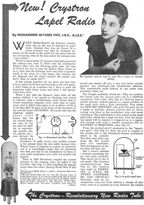
New! Crystron Lapel Radio
|
|
Admittedly, with all the reading I have done of vintage electronics magazines, news of this Crystron (crystal-electron) vacuum tube device invented by Mr. Mohammed Ulysses Fips, as reported in the April 1947 issue of Radio Craft magazine, evaded my attention. The article came only a couple months after publication of the 40th anniversary edition that celebrated Dr. Lee de Forest's invention of the Audion tube. According to Mr. Fips, his Crystron one-upped the Audion by virtue of its containing a small amount of radio isotope which obviated the need for the traditional "B-battery" concept also developed by de Forest to supply a high voltage for driving the output stage circuit. While not capable of powering a concert hall audio speaker system, it did make possible use of a small speaker as a nearby personal listening device rather than requiring headphones or earbuds. Without divulging the most critical and closely-held details of the Crystron as the U.S. Patent Office was still evaluating its merit, Fips provides enough insight into its construction and operational principles to make you wonder whatever happened to it, given that at last to my knowledge there was not a host of applications and products that incorporated a Crystron. Maybe it eventually evolved as a successful product under a different name, possibly having succumbed to a nefarious patent thief. Dr. de Forest was the victim of such ploys, as were many in that era. New! Crystron Lapel Radio
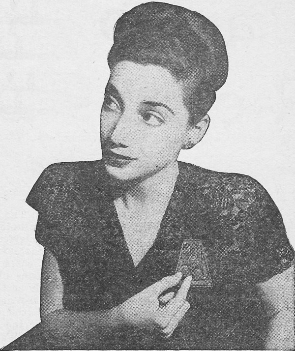
The Crystron receiver may be worn like a piece of costume jewelry.
When Radio-Craft's big January number came out, no one was as dejected as yours truly. Granted that Lee de Forest IS a great inventor and that he certainly deserves all the credit in the world for his many marvelous inventions, why all the fuss about his vacuum tube - the audion? What's so good about it? Anyone could have invented the audion - yes, even I! There was the well-known Edison effect and the Fleming diode tube. All that de Forest did was to take the Edison effect, brush up on it, then take the Fleming valve and stick a question mark, in the form of a bent paper clip, between the hot filament and the plate - presto! the audion was born! Easy as apple pie! ** If this sounds boastful, let me show you how easy it IS to outfox de Forest and beat him at his own game. I don't claim to be a genius - all I have is good old American radio horse sense and what I did anyone could have done. When I saw that fat January issue with all the audion hubbub, I set myself to thinking and vowed to discover such a revolutionary radio device that it would completely outmode every radio tube in existence! And it didn't take years to do it either - I did it in 33 days flat! So here is the story of the invention of the revolutionary Crystron: Everyone who has the slightest notion about radio knows that the old crystal detector was by far the best for fidelity in reproducing sounds - music, speech, etc. - ever devised. Its clarity as a translator of radio waves into audible sounds is far greater than the best radio vacuum tube. What's more, it requires no power, no batteries, and it is exceedingly cheap. But its drawback was that you had to use headphones to listen to your radio programs - you could not amplify the signals.
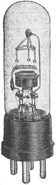
Gernsback Crystron Lapel Radio Prototype
Fig. 1 - Gernsback Interflex, 1925.
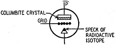
Fig. 2 - A grid crystal tube.
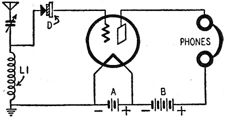
Fig. 3-The simplest Crystron circuit.
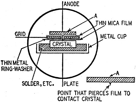
Fig. 4 - A capacitive-grid crystal tube.
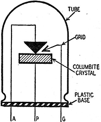
Fig. 5 - The Crystron in its final form.
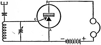
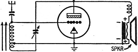
Fig. 6 - A battery-less Crystron receiver.
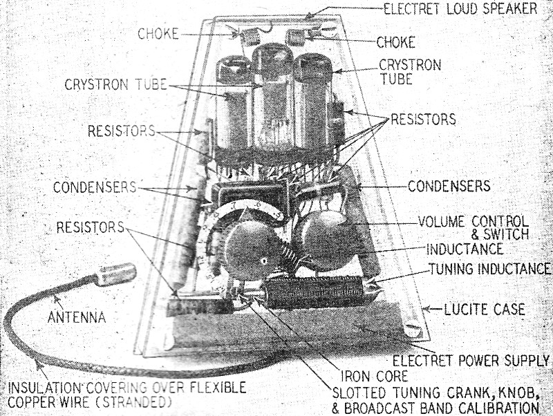
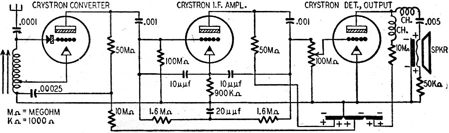
Fig. 7 - Crystron superhet with 3-segment electret and electret speaker, autodyne mixer circuit and bridged-T i.f. stage. Then in 1925 Gernsback coupled the crystal detector to the vacuum tube; he called it the Interflex, (See Fig. 1) This amplified the signals better than two tubes. During World War II this circuit was dusted off and, a new and better crystal detector was perfected - the Germanium detector. This combination made history in our radar sets, proximity fuses, etc. The thought suddenly struck me: Why not combine the crystal with the vacuum tube - all in a single component? This I did. (See Fig. 2.) Here we have a crystal detector - silicon, galena, or copper pyrites in the usual style, with a fixed catwhisker. Now comes the new big thought - the grid. The grid can be a single or multiple, sharply pointed wire or wires coming very close to the catwhisker wire - but never touching it. The combination is then placed in the usual glass bulb, which has a high vacuum. Now the incoming signal will be steered or triggered as in a regulation vacuum tube with a notable exception - no battery is required. (See Fig. 3). From the pointed grid I graduated to the "capacitive grid," (See Fig. 4). Here the grid is coupled to the crystal and to the thumbtack-shaped catwhisker which is the cathode. Two thin mica films separate the flat crystal from the catwhisker. This arrangement is better than the first one. But I wasn't satisfied - wanted something better and more powerful. That desire led to the final model: The Crystron (crystal-electron) (See Fig. 5). The Crystron was made by inserting a grid between catwhisker and crystal! Obviously such an arrangement could not work without a stream of electrons, such as is supplied by a hot filament. By coating the tip of the catwhisker with a speck of radioactive material and placing the parts in a high vacuum, we have a simple and extraordinarily powerful source of electrons. In addition I discovered a new exceedingly sensitive and stable crystal called Columbite, far better than Germanium, used in the best present-day crystal detectors. Basically, the Cystron requires no A or B battery for its operation. Indeed, a regenerative Crystron circuit drives loudspeaker with excellent volume on most local stations. (See circuit in Fig 6). Note that no batteries are used. A photograph shows the actual and historic auto-powered Crystron as first designed. Many radioactive substances were tried in the Crystron - thorium, uranium, radium, plutonium, and neptunium - the latter two radioactive elements being the ones used in the atomic bomb. (See photo, lower left, page 24). For practical purposes I finally found a comparatively cheap radioactive isotope, which gives excellent results. For security purposes, however, I cannot here divulge the exact substance used. I built a variety of different Crystrons, some with double radioactive catwhiskers, screen grids, double crystals, etc. It can be seen that the Crystron combinations are endless, as are its circuits - it is the beginning of an entirely new radio art, so vast that no one can foresee its ultimate end. Photo-electric Crystrons, television Crystrons, Crystron-Klystrons, Crystron-Magnetrons - all will soon appear to make this a glorious new radio age. In this article only a single practical application of the Crystron is presented - the Crystron Lapel Radio. This was easily designed to fit such a very small space, because no batteries whatsoever are used. It was found, however, that the output volume of the Crystron could be enormously increased if additional electric potential was used, particularly where more than one Crystron is employed. But instead of a B Battery, which soon wears out, I make use of the electret* principle. It is the first time that a multiple electret has been employed in a radio set to supply the necessary high voltage. * For further study of the electret, its principles and practical applications, see Radio-Craft, November, 1945, page 88. - Editor. Moreover the electret does not wear out - anymore than does a permanent magnet. Therefore we really have now, also for the first time a perpetual radio receiver that needs no batteries or outside power supply! Up to the time of my experiments, the electret had been merely a scientific curiosity though the Japanese used them in microphones during the war. They were made of fragile and perishable wax. I tried to make plastic electrets, but found that a special quartzite glass was far better than any material heretofore used. The Perpetual Crystron Lapel Radio uses three electrets in one block. (See Fig. 7). The common negative, or back, is covered with a thin sputtered film of silver. The positive side is divided in three areas, each with its sputtered silver film, and with insulating strips of uncoated glass between them. Dividing the positive area this way prevents any interaction between circuits. The radio is an unconventional superheterodyne. The oscillator coil is an ordinary permeability-tuned broadcast coil, with a tap for the crystode (cathode) of the converter tube. The signal input (antenna) is attached to the same circuit. No serious attenuation of the signal frequency results, because the coil tunes broadly and the intermediate frequency is low. The converter tube, like the hot-cathode types, is a multi-element device. A small Columbite rectifier crystal in its control-grid circuit rectifies the incoming signal and permits it to modulate the oscillations produced in the triode circuit. The oscillator is a modified Hartley, with plate at r.f. ground potential. Because a condenser direct from plate, to ground produced too strong oscillations, it was tapped off at a point on the plate resistor determined by experiment. After mixing in the converter, the signal goes to the second tube, an i.f. amplifier hooked up in a bridged-T circuit, which is tuned very sharply to 100 kc. Gain measurements with a vacuum-tube voltmeter are hard to make because the meter loads the high-resistance circuits, but the stage has a gain of at least 100 and may be nearly twice that. The measuring difficulty is practically the same as that the serviceman experiences in ordinary receiver circuits with the old 1,000-ohm-per-volt meter. The power amplifier has a larger radioactive element in its crystode, and has a lower amplification factor and internal resistance than the other tubes. I revived the almost-forgotten condenser, speaker for the little radio. This old speaker never had a fair chance, demanding as it did a high polarizing voltage at a time when there was nothing better than B-batteries to supply it. It consists of a thin metal sheet suspended close to and in front of a metal plate, with a high polarizing voltage between them, The voltage on the thin sheet is varied by the signal, causing it to be attracted and repelled by the heavy back plate. This vibration back and forth reproduces the speech or music. I used an electret for the back plate, and thus kept a voltage higher than 600 between it and the sheet of aluminum foil which formed the diaphragm of my improved speaker. Instead of the perishable rubber which was used in the old speakers as an insulating cushion between diaphragm and back plate, a war-developed plastic was used. As soon as I finished the construction of the Crystron Lapel Radio I took it over to the Editor of Radio-Craft and proceeded to demonstrate it to him. It had worked exceedingly well in the laboratory and brought in every station within 200 miles with earsplitting volume. Fiercely proud of my revolutionary invention, I expected a fat check for my article. I explained the new principle of the Crystron to the Boss, who listened interestedly, if incredulously. Finally near the end of my technical talk he interrupted me rather impatiently, as is his habit. Taking the big cigar from his mouth he snapped, "Well, Fips, let's hear that Lapel Radio, and make it snappy." Smilingly I turned the knob. Nothing happened. I muttered, "Loose connection, probably. It worked O.K. half an hour ago." I then opened the set and fiddled around with it, while perspiration began to drip from my forehead and hands - but I couldn't get a sound from the damned thing. In this excruciating predicament, every pore now exuded hot, burning perspiration. My fingers and hands moved like a slow-motion film - it seemed tortuous minutes before I could straighten out my body from its previous bent position. All the while the Big Boss, his face now an apoplectic purple, kept advancing menacingly. Already he had grabbed my precious Crystron Lapel Radio, which - as if by magic - had now grown as big as a coffin. He was holding it between his two huge hairy, ape-like hands and with an insane, laughing yell swung it up and crashed it with a fearful splintering sound down on my head ... When I came to I was in a white-walled room, lying on a high bed. My bandaged head was aching terrifically with a constant high-frequency throb. "What happened ... Where am I?" I murmured weakly. Minuteness of the receiver is seen by comparison with the hand. "You slipped on a banana peel and fell down the whole length of the subway stairs - all 32 of them. At the bottom your head hit the steel-clad edge of the last step and cracked your skull neatly - but not fatally," said the man in white. "Incidentally, this is the City Hall Hospital, and you had better rest now." "One more question, Doctor - when did it happen, and what day is this? "The accident occurred the day before yesterday, and you've been unconscious ever since. And today, if you didn't know it already, happens to be April first." * International Radio Expert; Author: Industrial Electronic Equilibrium. ** We are afraid Fips did not read the January issue of Radio-Craft at all. If he had, he would know that de Forest evolved the audion step by step from the Welsbach mantle to the final goal - the audion. The grid looks simple now - after de Forest invented it. The discovery of the New World looked easy, too - after Columbus had found it. - Editor.
Posted April 1, 2020
The Collected Works of Mohammed Ulysses Fips (note the misspelling of Ulysses) These Mohammed Ulysses Fips articles appeared in Radio−Craft and later in Radio−Electronics magazines, by in what I am sure is sheer coincidence all appear in April issues (beginning in 1944)!
|
|