Module 16 − Introduction to Test Equipment
Pages i,
1−1,
1−11,
1−21,
2−1,
2−11,
2−21,
3−1,
3−11,
3−21,
3−31,
4−1,
4−11,
4−21,
5−1,
5−11,
5−21,
5−31,
6−1,
6−11,
6−21,
6−31,
6−41, Index
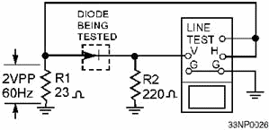
Figure 2-15. - Testing semiconductor diodes with an oscilloscope. The test signal applied to the crystal diode is also connected to the horizontal input of the
oscilloscope. The horizontal sweep represents the voltage applied to the diode under test. The voltage developed
across current-measuring resistor R2 is applied to the vertical input of the oscilloscope. Because this voltage is
proportional to the current through the diode being tested, the vertical deflection will indicate crystal current.
The resulting oscilloscope trace for a normal diode is similar to the curve shown in figure 2-16.
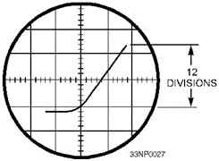
Figure 2-16. - Characteristic curve of a semiconductor diode. To test Zener diodes, you must use a higher voltage than the oscilloscope line-test signal. This test
can be made with a diode test set or with the circuit shown in figure 2-17. In this circuit, rheostat R1 is used
to adjust the input voltage to a suitable value for the Zener diode being tested. Resistor R2 limits the current
through the diode. The signal voltage applied to the diode is also connected to the horizontal input of the
oscilloscope. The voltage developed across current-measuring resistor R3 is applied to the vertical input of the
oscilloscope. The horizontal sweep represents the applied voltage, and the vertical deflection indicates the
current through the diode being tested. Figure 2-18 shows the characteristic pattern of a Zener diode. Note the
sharp increase in current at the Zener voltage (avalanche) point. For the Zener diode to be usable, this voltage
must be within limits specified by the manufacturer.
2-21
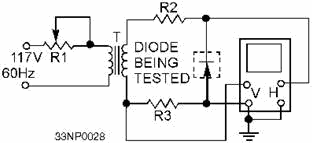
Figure 2-17. - Testing a Zener diode.
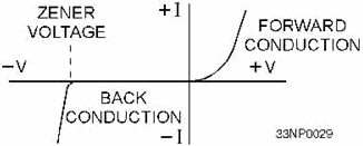
Figure 2-18. - Zener diode characteristic curve. TESTING TransistorS Most transistorized equipments use printed circuit boards
on which components are neatly arranged. This arrangement makes the transistors and other components easy to reach
while you are troubleshooting and servicing the equipment. While investigating with test probes, however, you must
be careful to prevent damage to the printed wiring. One of the outstanding advantages of transistors is
their reliability. Tube failures account for over 90 percent of the failures in electron-tube equipments.
Transistors, however, are long lived. This factor, among others, decreases maintenance required to keep
transistorized equipment operating. The techniques used in testing transistorized equipment are similar to those
for maintaining electron-tube circuits. Basically, these techniques include several checks and inspections.
Power Supply Checks
When using test equipment to localize a trouble, you should check the power supply to see that its output voltages
are present and of the correct values. Improper power supply voltages can cause odd effects. You will prevent many
headaches by checking the power supply first.
2-22
Visual Inspection Visual inspection is a good maintenance technique.
Occasionally, you will find loose wires or faulty connections, making extensive voltage checks unnecessary.
Transistor Checks Transistors can be checked by substitution. Transistors, however, have
a characteristic known as leakage current, which may affect the results obtained when the substitution method is used. The leakage current may influence the current gain or amplification factor of the transistor.
Therefore, a particular transistor might operate properly in one circuit and not in another. This characteristic
is more critical in certain applications than in others. As the transistor ages, the amount of leakage current
tends to increase. One type of transistor checker used is the semiconductor test set. This test set can be used
either for in-circuit or out-of-circuit tests or for collector leakage current or current gain. You should use
extreme care when substituting transistors. More and more transistors have specific current and breakdown voltage
requirements that may affect how they operate within a given circuit. Q-12. As a transistor ages, what happens to the leakage current? Voltage Checks
Voltage measurements provide a means of checking circuit conditions in a transistorized circuit just as they do in
checking conditions in a tube circuit. The voltages, however, are much lower than in a tube circuit. The bias
voltage between the base and emitter, for instance, is usually 0.05 to 0.20 volts. When making checks, observe
polarity.
Resistance Checks Transistors have little tendency to burn or change value because of low
voltage in their circuits. They can, however, be permanently damaged by high-voltage conditions that occur when
the collector voltage is increased. They can also be permanently damaged when the ambient temperature increases
and causes excessive collector current flow. Transistors are easily damaged by high current; therefore, resistance
measurements must not be taken with an ohmmeter that provides a maximum current output in excess of 1 milliampere.
If you are not sure that the range of ohmmeter you want to use is below the 1 milliampere level, connect the
ohmmeter to a milliammeter and check it. See figure 2-19 for a method of measuring the current from an ohmmeter.
2-23
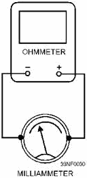
Figure 2-19. - Measuring current passed by an ohmmeter. Resistance measurements usually are not made in transistorized circuits, except when you are checking
for open windings in transformers and coils. When a resistance check is required, the transistors are usually
removed from the circuit. Resistance checks cannot test all the characteristics of transistors, especially
transistors designed for high frequencies or fast switching. The ohmmeter is capable of making simple transistor
tests, such as open and short tests. Refer to NEETS, Module 7, Introduction to Solid-State Devices and
Power Supplies, for a review of transistor and semiconductor terms and theory.
Summary The important points of this chapter are summarized in the following paragraphs: The
BEL is a unit that expresses the logarithmic ratio between the input and output of any given
component, circuit, or system and can be expressed in terms of voltage, current, or power. Any figure
expressed in bels can be converted to DECIBELS by multiplying the figure by 10. The decibel cannot be used to
represent actual power, only a ratio of one power to another. The abbreviation dBm is used to represent power
levels above or below a 1 milliwatt reference level. A BOLOMETER is a device that
undergoes changes in resistance as changes in dissipated power occur. The two types of bolometers most often used
are the barretter and the thermistor.
Frequency MEASUREMENTS can be divided into two broad categories: mechanical-rotation frequency
and electrical-output frequency measurements.
2-24
MECHANICAL ROTATION frequency is measured using a device called a TACHOMETER. Three
basic tachometers are used for measuring mechanical rotation frequency - the CENTRIFUGAL tachometer, the
CHRONOMETRIC tachometer, and the STROBOSCOPIC tachometer. ELECTRICAL-Output frequencies
of ac generators can be measured by VIBRATING-REED devices or Tuned Circuits. Audio FREQUENCIES
can be measured by a process known as ZERO BEATING. This is done by matching an unknown signal with a locally
generated signal of the same frequency obtained from a calibrated high-precision oscillator. As the two
frequencies are brought closer to the same value, they reach a point of zero beat. This is when the frequency
generated in the oscillator is equal to the frequency of the unknown signal being measured. Another term for zero
beating is HETERODYNING.
WAVEMETERS are calibrated resonant circuits used to measure frequency. Any type of
resonant circuit can be used in wavemeter applications. The type used depends on the frequency range for which the
meter is intended. For measuring frequencies in the microwave range, the CAVITY WAVEMETER is the type most
commonly used.
2-25
The CATHODE-RAY OSCILLOSCOPE and the SPECTRUM ANALYZER are used to perform WAVEforM
ANALYSIs. A typical BACK-to-forWARD-Resistance ratio for a diode is 10 to 1.
2-26
Answers to Questions Q1. Through Q12. A-1. Bel. A-2. dBm. A-3. 4 mW.
A-4. Dummy load or dummy antenna. A-5. Barretter and thermistor.
A-6. It increases. A-7. Beat frequency. A-8. Wavemeter.
A-9. Oscilloscope and spectrum analyzer. A-10. Spectrum analyzer.
A-11. 10-to-1 ratio. A-12. It tends to increase.
2-27
| - |
Matter, Energy,
and Direct Current |
| - |
Alternating Current and Transformers |
| - |
Circuit Protection, Control, and Measurement |
| - |
Electrical Conductors, Wiring Techniques,
and Schematic Reading |
| - |
Generators and Motors |
| - |
Electronic Emission, Tubes, and Power Supplies |
| - |
Solid-State Devices and Power Supplies |
| - |
Amplifiers |
| - |
Wave-Generation and Wave-Shaping Circuits |
| - |
Wave Propagation, Transmission Lines, and
Antennas |
| - |
Microwave Principles |
| - |
Modulation Principles |
| - |
Introduction to Number Systems and Logic Circuits |
| - |
- Introduction to Microelectronics |
| - |
Principles of Synchros, Servos, and Gyros |
| - |
Introduction to Test Equipment |
| - |
Radio-Frequency Communications Principles |
| - |
Radar Principles |
| - |
The Technician's Handbook, Master Glossary |
| - |
Test Methods and Practices |
| - |
Introduction to Digital Computers |
| - |
Magnetic Recording |
| - |
Introduction to Fiber Optics |
| Note: Navy Electricity and Electronics Training
Series (NEETS) content is U.S. Navy property in the public domain. |
|


