Quasi-Optical Short Waves - Electron Oscillations
|
|
These days we would hardly think of electromagnetic radiation in the 5 cm wavelength realm as being "quasi-optical" as far as circuit-based manipulation is concerned. Optical wavelengths begin at around 6,300 Å for red light, which is 6.3x10⁻⁵ cm, or 630 nm. The 5 cm wavelength used an example in a 1932 article in Short Wave Craft magazine is equivalent to 6 GHz. 6 GHz was an extraordinarily high frequency to be using for communications back then, and the author did not intend to liken it to anywhere near visible light. Instead, his terming its properties as "quasi-optical" referred to how the waves interacted with physical objects; e.g., reflection, refraction, absorption, and scattering. Barkhausen oscillations were a popular subject of the era, as I pointed out recently in the article "The Spook - Another Weird Effect to Haunt TV." Quasi-Optical Short Waves - Electron Oscillations
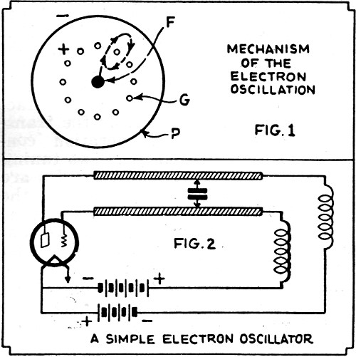
Fig. 1 shows path of an electron between filament and negatively charged plate in an electron oscillator. Fig. 2 - Hook-up of simple "electron oscillator."
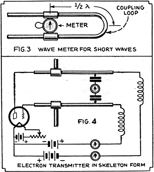
Fig. 3 - How to construct ultra-short wavemeter. Fig. 4 - Schematic diagram of an electron oscillator. By C. H. W. Nason What is the wavelength of a '99 tube? What is the basic action occurring in an electron oscillator? What conditions or factors govern the frequency of such an oscillator? How are the signals from such an oscillator received? The waves from 10 meters down to 5 centimeters are often referred to as the "Quasi-Optical range" (the inference may be gleaned from the dictionary they are "near-light" waves). These waves may be treated in many cases as light waves - particularly in the shorter ranges, where they may be reflected from metallic bodies having either plane surfaces or specific curvatures for directive transmission or reception. The waves have been acted upon by lenses made from dielectric materials (Bakelite for example) in such a manner as to demonstrate the fact that they closely resemble in behavior light waves, more usually thought of under the classification of "Optical." By means of special circuits, devised for the utmost of simplicity and efficiency, the normal vacuum-tube oscillator may be employed with good effect at wavelengths as low as 1 meter! Below this the stray tube and circuit capacitances are much in evidence, and the classical circuits are rather hopeless. In the lower range - speaking now in terms of wavelengths rather than frequencies, to simplify matters - the "electron oscillations" of Barkhausen and Kurz, and of Gill and Morrell, are most effective. Although these oscillations are known to the physicist, very little may be found regarding them in standard works on radio. It is necessary, therefore, that we first consider the mechanics of these oscillations, before entering into a more detailed exposition. The Mechanism of the Electron Oscillation Before going further, it is well to state that the most satisfactory tubes for use in these oscillators are those having concentric elements - cylindrical plates, etc. These are the '99, the '27, the '52 (more ambitious, of course) and certain of the tubes provided the government by various organizations during the war. Karplus in the General Radio Experimenter for May, 1931, indicates success with the G.E. "CG-1162" which is available from many radio salvage organizations. Electron oscillations may be obtained with other tubes specially developed for the service but, quite naturally, our interest rests with those tubes available for experiment. With the electron oscillators, the determination of frequency no longer rests upon the inductance and capacitance values of a tuned circuit, but rather on the electrostatic forces acting upon the individual electrons given off by the filament, and the resultant time element. Fig. 1 indicates the inter-electrode spacing of a triode (3-element tube) of the usual character. Note that the grid is positive and the plate negative, with respect to the filament. An electron, leaving the filament or cathode, is accelerated toward the grid by virtue of the grid's positive potential. The majority of these accelerated electrons will pass through the grid's mesh and, by virtue of their momentum, will travel onward toward the plate until they reach a point where the negative charge on the plate is sufficiently effective to halt their flight: they will then assume a backward path, toward the grid. They rejoin then the other electrons passing toward the grid, following a path somewhat as indicated in the figure. The length of the path taken and the initial acceleration are the criteria for determining the frequency of the cycle. The actual A.C. voltages, making up the oscillatory energy-cycle, are induced by changes in the grid and plate charges created by the moving electrons. The original formula of Barkhausen covering the wavelength of the oscillations - barring factors too complex for inclusion in our discussion - is as follows:
where "d" is the distance between electrodes and "E" the voltage. (The equation is for the original two-element tube of Barkhausen and Kurz, and not for a triode.) The Barkhausen oscillations are independent of the circuit constants, to all intents and purposes. Circuits for Producing Electron Oscillations
Fig. 5 - Shows antenna placed in focus of a parabolic reflector. Fig. 6 - Arrangement of directive aerials with reflectors.
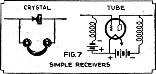
Fig. 7 - Receivers for laboratory work may be quite simple, as shown in diagram above.
Fig. 8-A - How apparatus is connected to make a super-regenerator "receiver" for electron oscillations.
Fig. 8-B - Receiving circuit for electron oscillator signals (wave lengths such as 15 inches). Fig. 2 shows the circuit arrangement of an oscillator for producing the Barkhausen effect. The Gill-Morrell oscillations are true electron oscillations, but their frequency is determined by the distance "d" between the elements and the short-circuiting condenser "C." The change between the two types of oscillations may be effected at will by altering the circuit conditions. In the Gill-Morrell effect, the oscillation is due to the timing of the electron's orbits by the oscillating circuit formed by the Lecher wires. The Gill-Morrell oscillations are much stronger and are preferable to the simple Barkhausen type. The transition may readily be obtained by setting the distance equal to one-half the desired wavelength, and adjusting the voltages for the maximum oscillation. The Lecher wires should be calibrated directly in centimeters to check the wavelength - remembering of course that the accuracy is not great. Fig. 3 shows a "trombone" wavemeter for rough measurement of the emitted wave; this is useful in determining the transition point between the two effects. By replacing the milliammeter with a crystal detector and phones, the device may be used to monitor modulated signals. Electron Transmitters In Fig. 4 there is illustrated a more complex arrangement of the original figure, showing the oscillator circuit. To this, it will be seen, there has been added an antenna; this should be positioned exactly one-fourth of a wavelength away from the bridging condenser. This places the antenna approximately in the center of the Lecher wire, where the Gill-Morrell oscillations are used, and at an indeterminate distance, depending upon the wavelength of the oscillations generated. The antenna is formed by two copper or brass rods clamped to the Lecher wires by a movable slide. They should be 1/4-wavelength long, and might be "tromboned" for ready variation. The grid-current meter should be of the order of 0-100 milliamperes while a 0-1-ma. meter may be used in the plate circuit. The. oscillatory current may be measured by a 100-ma. thermal milliammeter; the condensers are 0.001-mf. mica units. The R.F. chokes are simply wound from annunciator wire on a broom handle, and slid off. They are somewhat like the pretty curlicues that we used to employ to connect up buzzers and what not, before we had "wireless" to play with. In tuning the transmitter, the maximum oscillation is indicated by a maximum reading of the plate milliammeter. The antenna may be backed by a parabolic reflector of the type shown in Fig. 5, with the antenna situated at the focal point. (See the preceding issue of Short Wave Craft - page 254, Dec.-Jan., for details, of a parabolic curve.) Other types of directive antennas may be employed by the "ham" desirous of going deeply into the operation of the system. A reference to the article by Yagi, in the June, 1928, I. R. E. Proceedings will yield much data on the use of directive antennas at such short wavelengths. The directive effect of the reflector may be greatly increased by employing an arrangement such as that indicated in Fig. 6, at both transmitter and receiver; the rods used in the director chain are 1/2-wavelength long, and spaced 1/4-wavelength apart. The metallic reflector may be replaced by a system of five 1/2-wave length rods arranged in a parabola, at the focus of which the antenna is placed. Receivers for Electron Oscillations Because of the relatively low frequency stability obtained, little success will be achieved with electron oscillators for communications where straight C.W. is employed; although with A.C. on the filament, the hum modulation will be so great as to alter these conditions by creating an interrupted continuous-wave effect. Receivers for intramural (laboratory reception) work may be quite simple - as shown in the two circuits shown in Fig. 7. It is also possible to achieve high sensitivity in the receiver system by means of the "super-regenerator." Such a circuit arrangement is shown in Fig. 8-a. The most practical arrangement is that of employing another electron oscillator, almost identical with that employed as it transmitter. Indeed, a "changeover," of such type that a single oscillator may be used for both transmission and reception, may readily be effected. The most logical arrangement is that shown in Fig. 8-b, where the circuit constants are clearly indicated. The antenna is approximately 1/4-wavelength in dimension, and attached directly to the plate of the tube. Here it might be mentioned that any good tube socket may be used, and that "de-basing" of the tubes (as usual when extremely short waves are desired from the more usual oscillators) is unnecessary. The output of the receiver may be taken by means of a pair of phones, or by a transformer feeding a standard A.F. amplifier in the plate circuit of the receiver, as shown. The best tube to be used in the receiver is perhaps the '99, because of the extreme portability obtainable. Phone Modulation With the Electron Oscillator Telephonic modulation of the electron transmitter is achieved in the plate circuit, by substituting a modulation or microphone transformer for the phones shown in the receiver schematic. It is not necessary to provide a speech amplifier, although it is best to do so where long-range operation is desired. It should be remembered that a variation in the plate voltage of the oscillator effects a frequency change rather than - or as well as - an amplitude change. The modulation achieved is not so perfect, therefore, as in the case of the usual oscillators. Telephone communication has been achieved up to distances of about twenty miles with "electron transmitters," and telegraphic communication is possible over much greater distances. When we consider the fact that all possible forms of modulation involve a frequency shift, it is surprising that good quality can be obtained. Nevertheless, the quality of speech is quite good. Tubes and Voltages to Be Used The following table gives some idea of the voltages to be applied for various tubes and the oscillation wavelength to be expected. All tubes of a given class do not function as electron oscillators and many tubes must be operated with trick filament potentials. With the '27 the filament voltage should be rather low; whereas, in the case of the '99, best results seem to be obtained when the filament is completely deactivated and operated at a high voltage. The grid current is high in all cases, and the frequency range may be limited by the voltage which can be applied without melting the grid - or by the effects of grid emission. Wavelength 45-50 cms. (17.7 to 19.6 inches) 40 to 75 cms. (15.7 to 29.5 inches) 40 to 75 cms. (15.7 to 29.5 inches) Constructional Hints The whole outfit may be laid out on a breadboard, with Lecher wires about one meter (39.37 inches) long, made from heavy copper rod, mounted on G.R. stand-off insulators. Copper clamps spaced with Bakelite strips may be used to provide riders for the short-circuiting meter, or condensers, so that they may be readily slid along the Lecher wires. The plate and grid voltages should be made continuously variable by the use of potentiometers, and the necessary meters should be provided for taking readings. All work with electron oscillations is of a highly experimental nature, and no specific data can be provided with a sure-fire operation guaranteed. The experimenter undertaking this work should have had considerable experience with radio equipment, if any hope of success is to be held out to him; it is no game for the tyro.
Posted May 21, 2020 |
|