The Yagi Antenna |
||
Contributors to the Wikipedia article on the Yagi-Uda antenna credit Japanese professor Shintaro Uda primarily for the antenna's development, with Hidetsugu Yagi having played a 'lesser role." Other sources assign the primary role to Yagi. Regardless, history - and this article's author, rightly or wrongly, has decreed that this highly popular design be referred to commonly as the Yagi antenna and not the Uda antenna. I don't recall seeing advertisements for 'Uda' television or amateur radio antennas. Harold Harris, of Channel Master Corporation, does a nice job explaining the fundamentals of the Yagi antenna. The Yagi Antenna By Harold Harris, Channel Master Corp.
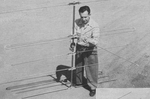
Fig. 1 - A five-element Yagi using a 3-conductor, 600 ohm folded dipole. Feed points are in the lower conductor of the folded dipole.
Fig, 2 - How the center conductor can be removed from folded dipole in order to permit its utilization as a connecting rod in stacking.
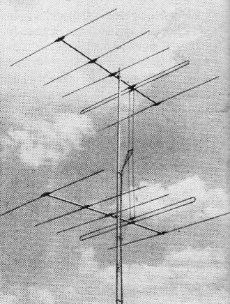
Fig. 3 - Stacked five-element Yagi antennas with center conductors removed from folded dipoles and used to provide half-wave stacking.
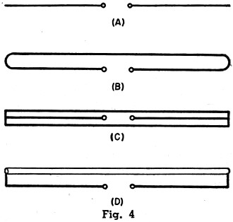
Fig. 4 - Types of dipole antennas. See text.
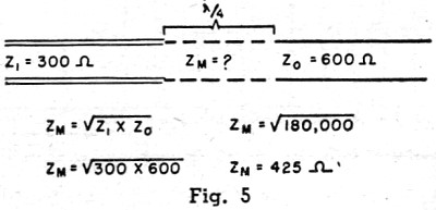
Fig. 5 - Method of choosing correct quarter-wave transformer to match 600 ohm line to the commonly-used 300 ohm line.
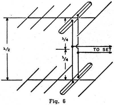
Fig. 6 - Common method of stacking two Yagis at a half wave. See text for details.
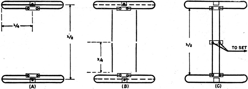
Fig. 7 - (A) Two 3·conductor folds spaced a one-half wave. (B) The two folds with center conductor removed preliminary to using conductors as stacking rods. (C) The two folds used as conventional folded dipoles with the center conductors used as connecting rods.
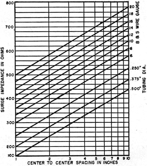
Fig. 8 - Characteristic impedance versus spacing of commonly-used conductors.
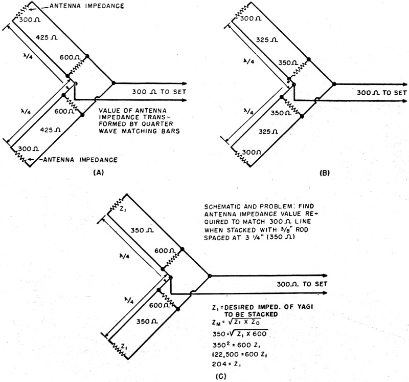
Fig. 9 - (A) Schematic of Fig. 6 with impedance values included. (B) Schematic showing resultant impedance of two 300 ohm Yagis stacked using 3/8 inch rods spaced at 3 inches (325 ohms). (C) Schematic and problem: Find antenna impedance value required to match 300 ohm line when stacked with 3/8 inch rod spaced at 3 1/4 inches (350 ohms). One of the best TV fringe area antennas. Article covers methods of stacking and details of how to obtain correct antenna-receiver impedance match. The emergence of the Yagi antenna as one of the most popular television receiving antennas for use in the fringes of one or two-channel service areas has been one of the most interesting antenna developments of the year. The Yagi antenna was developed by Hidetsugu Yagi, a Japanese physicist, and, ironically, it found widespread use against the Japanese as a mobile radar antenna during World War II. The unique feature of the Yagi antenna is that only one element is driven and the one or more elements in the field of the driven element are parasitically excited. Due to length and spacing, these parasitic elements act as directors or reflectors. The term "Yagi" was originally used to designate any antenna using a parasitic element but present terminology applies to antennas having two or more parasitic elements. The success of the Yagi as a television receiving antenna has been somewhat dimmed by the difficulty involved in stacking commercial models so that the additional gain contributed by the second bay can be fully realized. Since the problem lies chiefly with impedances it might be well to review the characteristics of the various dipoles used in Yagi antennas. In a simple folded dipole (Fig. 4B) the current divides equally between the two conductors. Thus, at the feed point only one half the current is flowing that would flow in a straight dipole being fed with the same power. Since the impedance varies with the square of the current the reduction of the current by half means that the impedance is raised four times. A straight dipole (Fig. 4A) has an approximate impedance of 75 ohms thus the two-conductor folded dipole has an impedance of 300 ohms. In a three-conductor folded dipole (Fig. 4C) the current is reduced to one-third at the feed point and thus the impedance is raised nine times or to approximately 600 ohms. In the folded dipole using conduc-tors of different diameters (Fig. 4D) if the driven conductor is the smaller of the two, a larger percentage of the current flows in the conductor having the greatest diameter. The current at the feed point is reduced by factors relating to the ratio of the diameters and the spacing between them. In any parasitic array the addition of reflectors or directors lowers the antenna input impedance. In general, each additional parasitic element reduces the impedance still further. The amount of the reduction depends chiefly on the spacing between the added element and the fed dipole. It will thus be seen that the use of a straight dipole in a Yagi array consisting of three or more close-spaced elements is not practical in television receiving applications since in this in-stance the impedance might drop to as low as 25 ohms. In most Yagi arrays the addition of more than three directors no longer affects the impedance adversely since the distance between he additional director and the driven element is too great for coupling. There is an advantage to be realized in the form of increased directivity. The use of a 300 ohm folded' dipole in a television receiving Yagi is preferred over a straight dipole because the higher input impedance comes close to matching the popular 300 ohm transmission line. It must be emphasized that the reduction in antenna impedance depends equally on spacing and the number of parasitic elements. As a matter of fact, a wide-spaced, five-element Yagi can have a higher impedance than a close-spaced, three-element Yagi. From a practical standpoint and for mechanical considerations, the cross arm on television receiving Yagis is usually restricted to a half wave-length, particularly on the low band. This, in turn, means close coupling between the elements and, therefore, a low impedance results. In most commercial Yagis a dipole having an impedance of approximately 600 ohms is required. This value is usually obtained in a five-element television receiving Yagi by using one of two types of dipoles. One type is the three-conductor folded dipole (Fig. 4C) which has an impedance of approximately 600 ohms. The second arrangement utilizes the two diameter folded dipole (Fig. 4D) which should have a ratio of 3 to 1 in order to provide the desired 600 ohm impedance. Up to now we have considered some of the problems involved in the design of a television receiving Yagi. In many cases, however, the gain realized by the five-element Yagi is insufficient for fringe areas. The small amount of gain obtained by adding more directors is not worthwhile. The most common procedure, then, is to stack these five-element Yagis. It is the specific purpose of this article to point out why, in most cases, this is an unprofitable and an inefficient procedure. A Yagi that matches a 300 ohm line as a single bay cannot be stacked and still match a 300 ohm line unless certain changes are made. In pursuing this topic, it is first necessary to discuss the characteristics of the linear quarter-wave transformer. The characteristics of this quarter-wave section of parallel wire transmission line are such that it has the property of matching unlike impedances so that there is no electrical discontinuity in the system in which it is incorporated. This characteristic is effective only for the frequency at which the transformer equals one quarter wavelength. The formula for determining the desired impedance for the quarter-wave matching transformer is:
where: ZM is the unknown matching impedance ZI is the input impedance, and ZO is the output impedance. As an example, let's determine what impedance is necessary to match 300 ohms to 600 ohms in the problem of Fig. 5. These particular values were chosen for this problem because they are the ones involved when stacking two Yagis each having an impedance of 300 ohms. The problem involves the antennas shown in Fig. 6 and its schematic representation with the values superimposed in Fig. 9A. Each antenna must have its impedance stepped up to 600 ohms at the junction point where the 300 ohm line to the set is connected. The two transformed impedances of 600 ohms each are in parallel. Paralleling these impedances gives an impedance of 300 ohms at the junction point, the exact impedance required to match the 300 ohm transmission line. At first glance the problem appears simple. It would seem that all that is necessary is to use two sets of 425 ohm quarter-wave matching transformers to stack the two 300 ohm Yagis. However, let us first consider how the characteristic impedance of parallel wire transmission is determined. The formula is: Z = 276 log 10 (2S/d) where: S is the spacing between conductors, and d is the diameter. In other words, the impedance depends on the diameter and spacing. Bear in mind that practically every commercial stacked Yagi is claimed to match 300 ohm line and uses 3/8 or 1/2" tubing for matching bars. These bars are usually spaced 3" apart. The chart of Fig. 8 shows the characteristics or surge impedances of the most commonly-used transmission line conductor sizes at various spacings. In order to stack 300 ohm Yagis it is necessary to use 425 ohm transmission line. In order to obtain a 425 ohm impedance using 3/8 " line, the spacing should be approximately 6 1/2". In order to get 425 ohms using 1/2" tubing, the spacing should be approximately 10". Since most commercial television receiving Yagis use 3/8" tubing spaced at 3", let's check the chart to determine the surge impedance of this line. The chart shows that the impedance is approximately 325 ohms. The schematic diagram of Fig. 9B shows that a 325 ohm transformer is tied to each 300 ohm Yagi, resulting in two parallel impedances of 350 ohms or a net impedance of 175 ohms at the junction point. Thus, the two single bay Yagis which match the 300 ohm line present a 2 to 1 mismatch under ordinary methods of stacking. Two solutions to this problem are possible. First, it is possible to use 425 ohm stacking harnesses constructed of wire. Referring to the chart of Fig. 8, it will be seen that for a 425 ohm line at 3" spacing #6 wire must be used. Second, the impedance of each Yagi can be lowered so that the 3/8" matching bars, with their characteristic im-pedance of 350 ohms, can be used to present two parallel impedances of 600 ohms. Schematically, Fig. 9C, the problem is as follows: If we can lower the impedance of the Yagi to approximately 200 ohms when stacking, this 200 ohm impedance will be transformed to 600 ohms by the 3/8" tubing matching bars. The two 600 ohm impedances in parallel result in a perfect 300 ohm match to the transmission line. The Channel Master Corp. has achieved these results by means of a mechanical arrangement. To obtain a total impedance of 300 ohms in a single bay Yagi, a three-conductor folded dipole is used. The 600 ohm impedance of the element is reduced to 300 ohms by the proper choice of spacing of the parasitic elements. See Fig. 1. The bottom section of the fold contains the feed points, for the following reasons. In stacking this Yagi the impedance is dropped to 200 ohms by removing the center conductor of the folded element, making it a conventional folded dipole. Since the tip-to-tip distance of the fold is one half-wave, the removal of the center conductor yields a pair of 3/8" quarter wave connecting bars. The same process is repeated on the other Yagi and a full set of connecting rods is obtained. (Fig. 2) These are then used to connect the two Yagis as shown in Fig. 3. The result is a Yagi which provides a perfect match to 300 ohm line either in its single or stacked ver-sion. In this way the full value of stacking is realized and an additional gain of 3 db is obtained.
Posted March 4, 2020 |
||