TV Receiver Conversion for Velocity Modulation
|
||
Velocity modulation, aka deflection modulation, of electronic images was evidently considered by some engineers to be potentially disruptive technology when this article was published in the April 1951 issue of Radio & Television News magazine. You can see from the pictures that the result is an image that today's digital software would render with an "emboss" technique. More vertical relief seems to be generated with the analog velocity modulation technique compared to what my graphics program does when embossing the original photo. At the bottom of the page is a velocity modulation video demonstration found on YouTube. See also "Velocity Modulation of Electron Beams," a May 1939 QST Article. TV Receiver Conversion for Velocity Modulation
Fig. 1 - Live subject reproduced by (left) velocity modulation and (top) by conventional intensity modulation. By M. A. Honnell and M. D. Prince Georgia Institute of Technology By merely adding a single switch and a few wires any electrostatic deflection type set can be converted. Although the operating principles of television system are now well established, in the early stages of the art a television system was developed which operated quite differently from those in use today. Prior to the perfection of the modern high-vacuum kinescope, the early gas-filled version of the cathode-ray tube was incapable of adequate grid control. In view of this fundamental limitation, the idea was conceived of operating the cathode-ray tube with constant beam current and applying the video voltage to the horizontal deflection circuit so that the picture information was supplied by changes in the horizontal scanning velocity of the fluorescent spot on the screen of the cathode-ray tube. This deflection-modulation principle was first proposed by Boris Rosing, a Russian teacher, in 1911, and a satisfactory working system was demonstrated by the German scientist, Von Ardenne, in 1931. Later, in 1933. the British workers Bedford and Puckle perfected an ingenious system which utilized a combination of deflection-modulation and intensity modulation.1 Following this period the field of deflection-modulation lay dormant; beam-intensity modulation had proved more advantageous and was developed to its present state of perfection. However, this field was recently reopened when research by the authors revealed that standard television programs transmitted by commercial stations could be reproduced with unusual results by use of deflection-modulation. A description of this work and a basic analysis of the underlying principles was presented to the 1950 National Convention of the Institute of Radio Engineers. In this present article, the circuitry is described and receiver modifications are shown so that the amateur experimenter can demonstrate this deflection-modulation reproduction on his own television set. This discussion is confined to the consideration of an electrostatic-deflection receiver, although deflection-modulation has also been demonstrated in the laboratory using magnetic deflection. However, since the high-voltage is usually obtained by fly-back pulse rectification, the conversion of a magnetic-deflection receiver is not recommended. In a receiver employing this type of power supply, any video signal inserted in the deflection circuit interacts with the anode voltage and causes distortion of the picture raster.
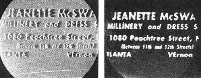
Fig. 2 - An example of printed material as reproduced by (left) velocity modulation as described in the text and (right) conventional intensity modulation techniques. The conversion of a National type NC-TV7M electrostatic-deflection receiver will now be considered in detail. The diagram shown in Fig. 3 illustrates the modifications which provide deflection-modulation reproduction. When the two-position switch S1 is in position 1, the circuit operates in the usual manner, in which case the video signal is coupled from the video amplifier V8 through coupling condenser C34 to the cathode of the kinescope. It is to be noted that in this receiver the kinescope is cathode-driven. When the switch is in position 2, the receiver is converted to velocity modulation reproduction. In this mode of operation, the video signal is removed from the kinescope circuit by opening the video signal lead immediately to the right of C34, and is then connected to the horizontal-deflection amplifier V14 through a small condenser Ca. This adds the video signal to the saw-tooth sweep voltage so that it is amplified along with the normal horizontal signal. Due to the amplification provided by the sweep amplifier, a value of Ca on the order of 3 μμfd. provides ample coupling between the video and deflection circuits. This value is not critical and a capacitance of 1 to 10 μμfd. will prove satisfactory. This capacitance may be provided by twisting together several inches of insulated wire. Since the kinescope beam current is no longer modulated by the video signal some other reasons must be provided for blanking the kinescope spot during the time required for retrace. During the vertical retrace period the spot is readily blanked by coupling the vertical sweep signal from V12 through Cb into the kinescope cathode circuit. A value of Cb = 1000 μμfd. was found satisfactory although the optimum value depends upon the receiver and can best be determined experimentally. The horizontal retrace lines were not objectionable so blanking was not provided for them. If the capacitance Cb is omitted, the velocity-modulated image will still be produced although the vertical retrace lines will be visible. It will now be instructive to consider the magnitude of video signal required to produce a deflection-modulated picture. Let us assume that the 7JP4 kinescope requires a peak-to-peak voltage of 800 volts for full horizontal deflection. Since a velocity-modulated image is produced by spot excursions on the order of one spot width, which corresponds to approximately 1/1000 of the raster width, a video signal voltage on the order of (800) / (1/1000) = 0.8 volt on the deflection plates will produce the desired image. If the deflection amplifier has a gain of 18, the desired voltage on the deflection plates is supplied by a voltage of 0.8/18 = .044 volt on the grid circuit of the deflection amplifier. By following the suggestions in this article, the experimenter will find that deflection modulation is capable of reproducing printed material and line drawings with acceptable legibility, although it does not achieve the fine contrast gradation produced by conventional television systems. A consideration of possible applications indicates that deflection modulation may offer some advantages for specific industrial and military applications due to its unique presentation of the subject matter. Furthermore, the possibility of circuit economy should be considered, since the numerical example worked out in a previous section indicates that the required video signal is of such a small magnitude that it could easily be obtained directly from the video detector, thus eliminating the video amplifier in the receiver.
Fig. 3 - Circuit diagram showing modifications of an electrostatic deflection receiver required to provide deflection modulation reproduction. When switch S1 is in position 1, the receiver operates in the normal manner. When S1 is in position 2, receiver is converted to deflection modulation reproduction. The only changes involved in converting the receiver are those connected directly with the switch. The preceding discussion naturally suggests the possibility of combining conventional beam modulation with deflection modulation in a television receiver. This type of presentation has been investigated in the laboratory and can easily be demonstrated on a receiver of the type shown in Fig. 3. This is accomplished by leaving the video signal lead connected to the kinescope circuit as in normal operation and at the same time coupling the video signal through Ca to the horizontal deflection amplifier to produce the velocity modulation. The images produced by this modified circuit exhibit an outlining edge on one side of bright objects and adds a crispness to the picture which seems to improve the apparent resolution. Deflection modulation is of further importance from a standpoint of standard receiver performance due to the fact that stray capacitances may exist in a conventional television receiver and produce some degree of spurious deflection-modulation in combination with the conventional presentation. In other words, due to faulty receiver design or failure of component parts, an undesired deflection-modulation image may be super-imposed on the regular television picture; thus causing some positional distortion and loss of contrast. This type of distortion may result in a halo effect similar to that caused by overshoot in the video section, or by ghost images caused by reflections and may therefore be improperly diagnosed. Research in the laboratories and by the experimenter may reveal additional points of interest since the full implications of the combination of deflection modulation with beam modulation are not completely apparent at this date. The writers are grateful to the Engineering Experiment Station at Georgia Tech for its financial support of the investigation of deflection-modulation television systems. References Wilson" J. C.; "Television Engineering," Pitman and Sons, Ltd., London, p. 102, 1937. Zworykin, V. K. and Morton, G. A.; "Television" Wiley & Sons, Inc., New York, p. 238, 1940. 1 - Deflection-modulation is customarily referred to as "velocity modulation" since the lateral velocity of the scanning spot is modulated in the horizontal direction. Unfortunately, however, the term "velocity modulation" has also gained acceptance in an entirely different sense, as the "velocity-modulated" klystron tube. When used with this latter meaning, it applies to the change in velocity of the electrons in the electron beam itself, such as would be produced by modulating the second-anode voltage in a cathode-ray tube. Velocity Modulation Demonstration (YouTube)
Posted September 29, 2023 |
||