Transmission Line Systems for FM & Television Home Receivers |
|
It is amazing to me how many times I read an article, whether in a vintage magazine like this 1947 issue of Radio News, or a current edition of QST, how when discussing maximum power transfer from a source to a load, the author states merely that the load impedance must equal the source impedance. The fact of the matter is that the source and load impedances must be the complex conjugates of each other in order for maximum power transfer to occur. That is to say that if the source has a complex impedance of R + jX, then the load must have a complex impedance of R - jX (and vice versa) in order for maximum power transfer to occur. If the source and load are purely resistive, meaning there is no reactive component (X = 0) to the impedance, technically that does not render the complex conjugate rule void, merely not of consequence in that case since -j0 = j0. Transmission Line Systems for FM & Television Home Receivers By C. Spear
The trend toward the use of higher frequency bands for FM and television has accentuated the importance of an efficient transmission line system between antenna and receiver. For as the frequency goes up it becomes increasingly difficult to feed an adequate signal from the antenna to the receiver and every effort must be made to conserve the comparatively little energy that is available. For this reason high gain directive antennas become necessary in many localities, and by the same logic highly efficient transmission line systems must be installed.
Fig. 1 - Power loss that occurs when a mismatch of antenna to receiver exists.
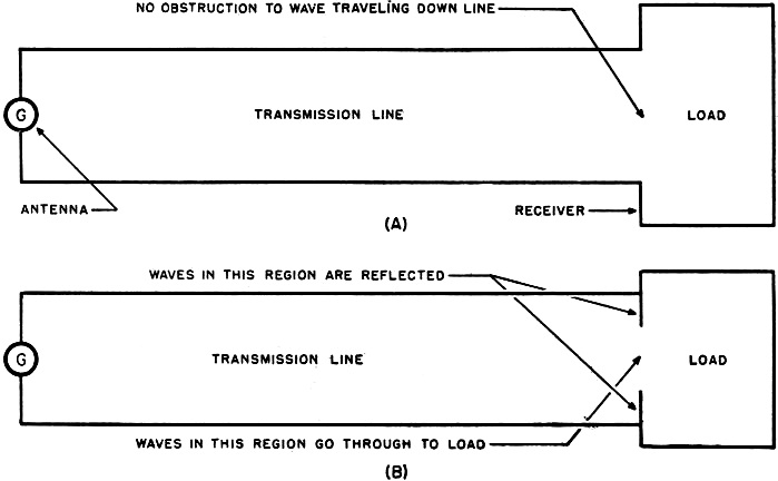
Fig. 2 - Semi-pictorial representation of what an electrical wave experiences at end of transmission line. (A) Perfect match and (B) when mismatch occurs. Fortunately, due to the advances made during the war in the high frequency cable field, low-loss transmission lines are available at low cost and if used properly will transmit the energy picked up by the antenna to the receiver without undue loss. However, the word "properly" has a great deal of significance, for another adverse effect of the increase in frequency is to make mismatching more critical and unless transmission lines are installed with a complete under-standing of this phenomenon they may be useless. This latter statement is intended only to emphasize the importance of the problem, and not in any way to indicate a difficult or hopeless condition, for the remedy is both simple to perform and understand. It is the objective of the author to unveil the mystery of matching and indicate the necessary calculations - requiring only a knowledge of fundamental multiplication and division, a straight edge, and some rule of the thumb procedures - with which the serviceman can solve virtually any of his transmission line problems. Included in these h.f. cable line problems that can easily be solved are; how to match any antenna to any receiver whether it be FM, television, radar, instrument landing, Army, Navy or any other electronic device; the effect of mismatches in terms of power or signal lost and how they can be corrected; how to intelligently select the appropriate transmission line; the "net" gain of directive antennas. In addition to a discussion of these questions some of the terms frequently used in the field will be clearly defined and converted into simpler expressions. "Decibels," one of the terms that will be used very frequently through-out this article, should be carefully defined. The decibel, abbreviated dB, is a numerical means of expressing the ratio of two compared powers or voltages. The following formula shows the relation between dB and power: dB = 10 log P1/P2, where P1 and P2 are the two powers compared; or in terms of voltages where E1 and E2 are the two voltages compared, dB = 20 log E1/E2 assuming that the two voltages are measured across equal impedances. For example, if a dipole antenna normally picks up 1 microvolt of signal, and, after adding directive arrays, it picks up 10 microvolts, then the gain of the antenna in dB due to the array is: 20 log 10 = 20 dB. Likewise, if a transmission line receives 10 milliwatts from an antenna, but delivers only 5 milliwatts to the receiver then the power lost in the cable is: 10 log 2 = 3 dB.
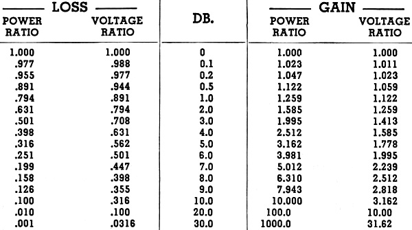
Table 1. Decibel conversion table. Power or voltage ratios can be converted to dB (or vice versa) without the need of logarithm tables or slide rule. In order to simplify the calculation of the decibels gained or lost see the conversion table (Table 1). From this table the reader can convert dB into power or voltage ratios or vice versa without the need of logarithm tables or a slide rule. There are three sources of power loss between antenna and receiver; mismatch between antenna and transmission line, attenuation or power loss in the transmission line, mismatch between transmission line and receiver. Antenna Mismatch One of the fundamental concepts of power transmission is that to obtain maximum power transfer, the output impedance of the generator (in this case the antenna) must be equal to the input impedance of the load (in this case receiver). Thus if the antenna resistance is 70 ohms, the receiver input should be 70 ohms, otherwise some of the power is lost. This is shown in Fig. 1, which is a graphic presentation of the signal voltage lost due to mismatch. At the present time consideration of the antenna impedance is very important for two reasons. In the first place receiver input and antenna impedances may vary to a great extent due to the lack of standardization amongst the various manufacturers, and due to the fact that many surplus Army and Navy receivers, designed for use with special antennas, may be circulated for general use. Secondly the addition of directive arrays changes the antenna impedance, and therefore it is necessary to calculate the power loss due to mismatch in order to determine the net or effective gain of the antenna. For example a typical problem of this type might be:
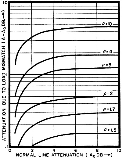
Fig. 3. Graph shows increment of attenuation as a function of the standing wave ratio (SWR) and normal line attenuation. Note in particular that the power loss due to transmission line mismatch does not become serious until the standing wave ratio is about 3:1.
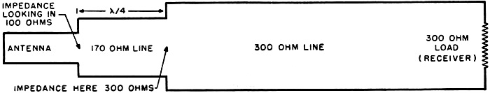
Fig. 4. Method of matching antenna to receiver via a quarter-wave transformer.
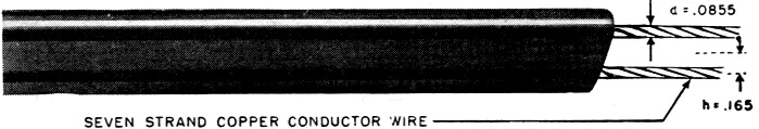
Intelin type K-200 antenna lead-in wire. The characteristic impedance of this wire is 200 ohms, while the attenuation at 30 mc. is .4 dB per 100 feet. Given: An antenna array which gives a 5 dB gain but changes the impedance from 300 ohms to 100 ohms. The original antenna was matched to the receiver - calculate the net gain. Solution: From Fig. 1 we note that a 3:1 impedance mismatch ratio results in signal which is 25 per-cent or 1.2 dB less. The net gain is therefore only 3.8 dB It then becomes a matter of mathematics whether the extra expense is worth the resultant gain. Of course as the mismatch becomes greater, the effective gain decreases, and the array becomes useless unless a matching network is utilized. However the matching can be performed rather simply, and the details will be discussed later in the article. Attenuation of the Cable The limiting factor on the minimum amount of power loss possible in any transmission line system is the attenuation or power loss of the cable; for any power lost due to mismatch can be corrected by means of matching circuits, but there is no remedy for the power lost due to the attenuation of the cable. Though there is no fixed standard, cable attenuation is usually rated in dB per 100 feet by most manufacturers. However, the power loss is proportional to the length of the cable. That is, 100 times more power is dissipated in a 100 foot cable than in a one foot cable. Therefore cable is sometimes rated in dB per foot instead of per 100 feet so that it will sound more efficient. For example, a h.f. cable whose attenuation is 20 dB per 100 foot (a very high value) could be rated at 0.2 dB per foot or 0.016 dB per inch. Another factor that affects the attenuation is the frequency at which it is used; for the power loss of any h.f. line increases approximately as the square of the frequency. This is an a essential fact particularly at the present time, since many of the cables are rated at the old FM frequency range of about 45 mc., and many manufacturers have not had a chance to reevaluate their cables so as to rate them at the new FM frequency band centering around 100 mc. Thus a 4-dB-per-100-foot cable rated at 30 mc., would be rated at approximately 6.8 dB per 100 feet at 100 mc. Matching the Transmission Line to Load All the sources of power loss discussed heretofore are not limited to high frequency receiver equipment, but apply equally as well to all types.
Posted March 7, 2023 |
|
")
 Conventional antenna systems with which most
servicemen are acquainted in standard broadcast work will not suffice in FM and
television installations. Each antenna system for these higher frequency bands must
be individually "engineered."
Conventional antenna systems with which most
servicemen are acquainted in standard broadcast work will not suffice in FM and
television installations. Each antenna system for these higher frequency bands must
be individually "engineered."