Student's Radio Physics Course - Series & Parallel Circuits |
|||
Not everyone who visits websites like RF Cafe is a seasoned electronics veteran. While I and most likely you, too, can do series and parallel circuit analysis (and series/parallel for that matter, possibly using Fourier or La Place transforms for reactive AC circuits) in our sleep, many are recently getting into the wonderful world of electronics who are just coming of age or have suddenly at a later point in life developed a passion for the craft. Accordingly, this article from Radio News magazine provides yet another tutorial on the fundamentals of series and parallel circuit analysis. Only resistors and basic Ohms law are covered. Student's Radio Physics Course - Series and Parallel Circuits This series deals with the study of the physical aspects of radio phenomena. It contains information of particular value to physics teachers and students in high schools and colleges. The Question Box aids teachers in laying out current class assignments Lesson Eleven - Series and Parallel By Alfred A. Ghirardi*
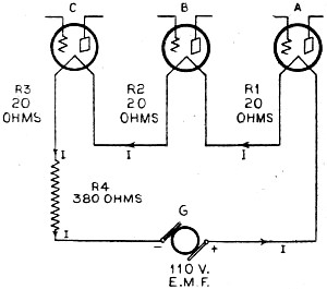
In order to have current flowing in any conductor the circuit must form a complete conducting path from the positive terminal to the source of e.m.f. around to the negative terminal (except in the case of a circuit with a condenser). In actual electrical circuits, electrical devices are connected in either of two ways - or a combination of the two. When they are connected one after the other in such a way that all of the current flows through each of them, they are said to be in series. Thus, in Figure 1 the filaments of all three of the vacuum tubes shown are connected in series with each other and with the resistor R1 across the 110-volt electric light circuit whose e.m.f. is maintained by the electric dynamo G. In such a circuit the total resistance of the entire circuit is equal to the sum of the separate resistances. Thus in Figure 1 if the resistances of the individual parts are as marked, the total resistance is: R = R1 + R2 + R3 + R4 + etc. (1) The total resistance is R = 380 + 20 + 20 + 20 = 440 ohms. The current I flowing in the circuit is: I = E/R = 110/440 = 0.25 amperes Another important fact regarding the series circuit is that the current is the same through every part of the circuit, since there can be no accumulation of current at any point along the circuit. If five ammeters were connected at the points marked I in Figure 1, they would all indicate the same current I, of 0.25 amperes. Also if a series circuit is opened or broken at any point the current stops flowing. A voltage drop occurs across each of the various resistances in a series circuit, depending on its resistance. If a voltmeter were connected across the filament of tube A, it would indicate E = I X R1 = 0.25 X 20 = 5 volts. This is the voltage drop or fall of potential across the resistance. Similarly, the voltmeter would read 5 volts if connected across the filaments of tubes B and C, since they both have resistances of 20 ohms. If it were connected across resistance R4 it would indicate E = I X R = 0.25 X 380 = 95 volts. The sum of all these voltage drops around the circuit is equal to 5 + 5 + 5 + 95 = 110 volts. This of course is equal to the voltage of the source of e.m.f. (G) which is causing the flow of current through the resistances. This illustrates another law of the series circuit: "The total voltage applied to the circuit is equal to the sum of the voltage drops across the individual resistances in the circuit." If any unit in a series circuit should become "short circuited," the current will increase because the total resistance of the circuit would be decreased. Notice from Figure 1 that the voltage drop across any resistance in the circuit de-pends upon its resistance. Thus even though the same current flows through all parts, the voltage drop across the 380-ohm resistance is 95 volts, whereas that across each 20-ohm resistance is only 5 volts. In radio receivers series circuits are very common in the plate circuits of vacuum tubes, as we shall see later. The adding of resistances in series is equivalent to increasing the length of the conductor, so that the total resistance is equal to the sum of the separate resistances. Parallel Circuits
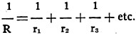
When parts of a circuit are connected in such a way that they form separate paths through which the current can divide, they are said to be connected in parallel, multiple, or shunt. Only a portion of the total current flowing from the source of e.m.f. flows through each path. Figure 2 shows a parallel circuit consisting of the filaments of three dissimilar vacuum tubes supplied with current forced through the circuits by the e.m.f. of the storage battery, E. Only a portion of the total current circulating through the battery passes through each of the circuits, but of course the sum of the number of amperes of current flowing in the three circuits is equal to the number of amperes of current circulating through the battery, since all the currents combine again. The actual current in each wire of the circuit is indicated on the diagram. Notice how the current coming out of the positive terminal of the battery divides to go through the tube filaments and then combines again at the negative line. Any number of electrical devices or circuits may be connected in parallel. The current returning to the negative side of the source of e.m.f. is exactly equal to the current leaving the positive side. The current is merely circulating through the circuits. The electrical devices connected in parallel may all have the same resistance or they may all have unequal resistances. If the resistances are equal, then it is evident that the total current will divide equally among the various paths, and the combined resistance of all the paths considered together is equal to one of the resistances divided by the number of resistances. Thus, if five resistances of 100 ohms each are connected in parallel, the combined resistance will be 100/5 = 20 ohms, since five paths are being presented to the flow of current instead of only one. When the parallel resistances are not equal, the combined resistance must be found by another method, in which the conductances of the various paths are considered. When the resistances are arranged in parallel, since several paths are being offered for the passage of the current, the effect produced is the same as if we were to increase the cross-sectional area of the original conductor. The current passing through the separate resistances is proportional to the conductivity of each path. It was earlier stated that the conductance of a circuit is equal to 1/R. That is, the less the resistance of a wire, the greater is its conductance or ability to conduct current. Conductance is expressed in mhos. Thus if the resistance of a conductor is 5 ohms, its conductance is 1/5 = 0.2 mho. The conductance of the entire parallel circuit is equal to the sum of the conductances of its individual branches. Thus if R stands for the combined resistance of the parallel circuit, and r1 r2, r3, etc., stand for the individual resistance of the parts of the parallel circuit, then
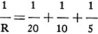
from which the combined resistance R may be calculated if the resistances of the individual branches are known. Thus in Figure 2 the combined resistance of the three filaments in parallel is:
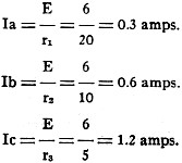
from which R = 2.9 ohms. Ans. Notice that the combined resistance is less than the resistance of any of the paths. This should be expected, of course, since even the path of the lowest resistance is having several additional conducting paths connected in parallel with it so that the resistance must be less. Additional paths increase the current-carrying ability of the circuit; that is, they decrease the resistance. We see that two or more equal resistances in parallel is merely a special case of parallel circuits. Equation (2) can be used for any condition of equal or unequal resistances. In a parallel circuit the voltage across each branch is the same as that across every other branch and is equal to that supplied by the source of e.m.f. The current which flows through each branch is simply equal to this voltage divided by the resistance of the branch. Thus in Figure 2, if the battery supplies an e.m.f. of 6 volts, the currents in the various branches are:
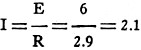
Therefore 1=0.3 + 0.6 + 1.2 = 2.1 amps. (This is the total current supplied by the battery.) As a check on this calculation we may calculate the total current directly from the value of the combined resistance of 2.9 ohms obtained above for the circuit. Thus
In a parallel circuit, if anyone of the branches is opened, current will continue to flow through the others. The conditions existing in parallel circuits are as follows: 1. The voltage is equal across all branches. 2. The combined resistance is less than the resistance of any branch of the circuit. 3. The total current is equal to the sum of the currents through all the branches. Parallel circuits are very common in radio receivers. In battery-operated receivers the filaments of the various tubes are usually connected in parallel across the source of e.m.f. (battery). In a.c. electric receivers the filaments of the tubes are connected in parallel across the filament winding of the transformer. The plate circuits are connected in parallel across the B supply unit. Question Box (supplemental material on page 46) Physics and science instructors will find these review questions and the "quiz" questions below useful as reading assignments for their classes. For other readers the questions provide an interesting pastime and permit a check on the reader's grasp of the material presented in the various articles in this issue. The "Review Questions" cover material in this month's installment of the Radio Physics Course.
Review Questions
1. Four vacuum-tube filaments having the following resistances are all connected in series: 20, 4, 5, 10. a. Draw the circuit diagram showing the connection. b. What is the total resistance of the combination? c. How much current will flow if the entire group is connected to a source of e.m.i. of 50 volts?
2. The resistances in question (1) are all connected in parallel. a. Draw the circuit diagram for this connection. b. What is the joint resistance of the combination? c. What current will flow through each filament if the source of e.m.i, is 6 volts? d. What is the total current taken from the battery?
3. The filaments of two 201A vacuum tubes having a resistance of 20 ohms each are connected in parallel. In series with this group is another filament having a resistance of 10 ohms. The entire group is supplied with current from a 6-volt storage battery. What is the combined resistance of all the tube filaments, and the total current flowing?
Quiz Answers
1b) Rtotal = (20 + 4 + 5 + 10) Ω = 39 Ω 1c) Itotal = E/R = 50 V / 39 Ω = 1.28 A
2b) Rtotal = 1/(1/20 + 1/4 + 1/5 + 1/10) Ω = 1.67 Ω 2c) I20Ω = 6 V / 20 Ω = 0.3 A I4Ω = 6 V / 4 Ω = 1.5 A I5Ω = 6 V / 5 Ω = 1.2 A I10Ω = 6 V / 10 Ω = 0.6 A 2d) Itotal = E/R = 6 V / 1.67 Ω = 3.6 A = (0.3 + 1.5 + 1.2 + 0.6) A = 3.6 A
Posted August 11, 2020 |
|||


 amps (which checks with
the value just calculated)
amps (which checks with
the value just calculated)