New Parasitic Beam Antenna Design |
|
Something about the moniker "plumber's delight"† for homebuilt antennas always appealed to me. In the early days of radio it referred to antennas built with threaded galvanized or soldered copper plumbing pipe or threaded black gas pipe. Today, it also includes structures that incorporate sections of cemented PVC pipe (with wire elements strung along or within them). A major issue with using threaded pipe is the potential for passive intermodulation products (PIMs) being generated at the dissimilar metal junctions (various degrees of oxidized metals). With as spectrally "dirty" as many transmitters as there were in the day, PIMs probably paled in comparison to what was spewed as a matter of course. The presence of PIM products, unless severe, is not usually noticeable in CW or phone operations, but with digital communications (very common in modern Ham radio), the bit error rate (BER) can be profoundly impacted by them. Note: Thanks to Lynn L. for reminding me that the original use of "plumber's delight" applied to antennas where the elements are physically (electrically) attached directly to the main mast (as opposed to being insulated from it). † Nowadays with plastic pipe being the default for plumbing water supply and wastewater lines, the term might not be as apparent to the younger crowd. New Parasitic Beam Design By R. G. Rowe, W2FMF Consulting Engineer
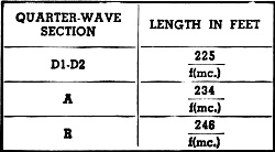
Table 1 - Formulas for calculating the various element lengths (shown in Fig. 1) for specific frequencies. The following article describes a four-element, ten-meter, close-spaced array based upon the Plumber's Delight, but having a distinctive feature in the way of adjusting element lengths not heretofore disclosed to the best of the writer's knowledge. While the design principles are not limited to any practical number of elements or element spacings, from a mechanical standpoint they can be best applied to arrays for 28 megacycles and higher, due to the relatively short element lengths required at these frequencies. The novel mechanical design arises from the method of staggering quarter-wave sections of each element along the central carrying tube, as shown in Figs. 1 and 3, thereby permitting simple adjustment of element length from the center of each half-wave section and eliminating the need for telescopic sections. The protrusion of the short length of the butt end of each quarter-wave section does not deleteriously affect the gain or pattern of the array. The beam is made entirely from aluminum, with the exception of one small piece of insulation in the "T" matching section, later to be described. The metal frame, elements, matching section, and feed line are all electrically connected, permitting a single, permanent ground connection to afford protection from lightning and static discharge.
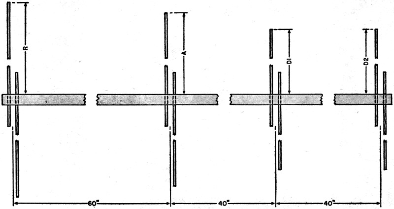
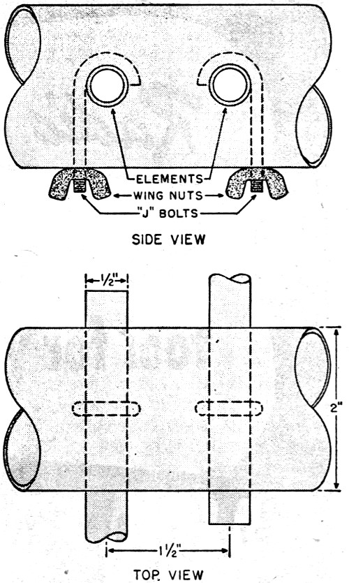
Fig. 1 - Diagram shows how the 12 foot, 2 inch o.d. aluminum tube is drilled to support the various antenna elements. Constructed unit is shown in Fig. 2. The central carrying structure, or "frame," for the particular ten-meter beam illustrated is made from a 12 foot length of 2 inch o.d. aluminum tube with a wall thickness of one sixteenth inch. An inspection of Fig. 4 shows how the tube is drilled at the spacings indicated in Fig. 1. A "stagger" distance of 1.5 inches was used in this particular embodiment, with 0.5 inch diameter thin-wall elements. The stagger distance should be minimized as much as possible, becoming progressively critical at higher and higher frequencies. The frame holes should provide a snug fit for the butt ends of the elements, yet permit them to slide when the clamping bolts are loosened. Small holes through the bottom of the frame, indicated in Fig. 4, are drilled to permit the insertion of the so-called "J" bolts. These bolts may be formed from eye bolts, "V" bolts or bent up from straight bolts. Tightening the wing nuts securely locks the elements in place, whereas loosening them slightly permits simple adjustment of the length of each quarter-wave section. The quarter-wave sections may be scribed or otherwise ruled off at their butt ends to facilitate reading the over-all length. In the illustrated beam, short pieces of friction tape were wound around each element near the butt end at a predetermined, measured length from the tip. Thus, by measuring the short distance from the frame to the tape, it is possible to balance the length of each section easily as well as to mentally calculate the over-all length rapidly, without using a long rule or tape to measure the tip-to-tip length. All adjustments and measurements may be made at the center of each half-wave section, greatly facilitating installation and tuning.
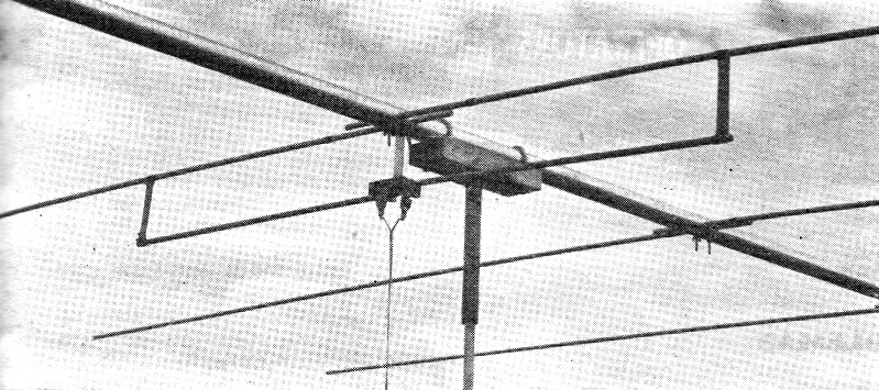
Fig. 2 - Photograph shows close-up view of "T" matching section.
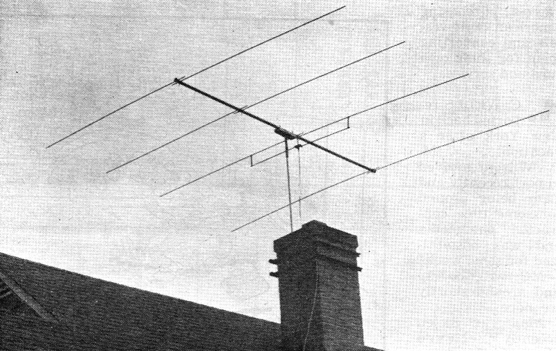
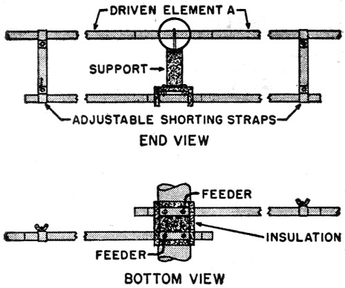
Fig. 3 - 10 meter antenna constructed by author. Main support is made of 1/2" galvanized pipe. Fig. 5 indicates a possible method for mounting the frame at its mechanical balance point on a short length of grooved 2 x 4 with "U" bolts. A pipe flange is screwed to the underside of the 2 x 4 to take a short 12 inch length of pipe, the i.d. of which just will slip over the o.d. of the supporting pipe, providing a bearing for rotation. In the illustrated arrangement, a 1/2 inch galvanized water pipe is used as the supporting pipe, for inasmuch as the array is close to the chimney bracket and the supporting pipe is short, greater rigidity is not required. Many other ways to support and to rotate such arrays have been fully described in the literature or will suggest themselves to the ham. In the illustrated mounting the tube frame was grounded to the pipe flange by a short length of copper braid, inasmuch as the supporting pipe and chimney bracket are permanently grounded to a vent pipe in the roof of the house for lightning protection. A potential method for rotating the array is to bring the base end of the supporting pipe through the roof. A section of small o.d. tube may be inserted inside the supporting pipe, mechanically secured to the 2 x 4 and provided at its lower projecting extremity with a wheel or lever for rotation. For this type of beam the "T" match, delta match or folded dipole feed is most easily adaptable. However, by drilling oversize the frame holes which carry the driven element, insulated bushings may be inserted at this voltage node to insulate each quarter wave of the antenna section from the frame so that other types of feed may be used. The "T" match shown in Figs. 2 and 6 was selected for this particular application and the "T" section is made up from two 33 inch lengths of 1/2 inch o.d. thin-wall aluminum tube, the same diameter as the elements. A small block of 1/2 inch thick bakelite serves to mechanically connect and electrically insulate the inner fed ends of the "T." The block is so dimensioned that the stagger distance of 1.5 inches is maintained in the "T" section and is supported from the tube frame for rigidity. The shorting straps, which are adjustable along the length of the elements and "T" section, are formed from one sixteenth inch thick aluminum sheet, 1 inch wide. They are provided at each end with a hole for the passage of a bolt and wing nut to tightly clamp the tubing. By loosening the two wing nuts on each shorting strap, each strap may be slid in or out along the length of the element to minimize standing waves on the feed line, after the beam has been tuned by anyone of several tuning procedures outlined in the various antenna handbooks. 300 ohm twin-lead type feeders are used with the illustrated beam and connected as shown in Fig. 6.
Fig. 4 - Construction details for mounting and fastening the antenna elements. Before final installation of the illustrated "T" section made from aluminum tube and aluminum shorting straps, a temporary "T" section using No.8 copper wire was used with excellent results. If a wire "T" section is used the vertical spacing may remain 4 inches and the distance "T" determined by noting the standing wave ratio. A convenient, qualitative check for standing waves on the twin-lead type line may be made by running a neon bulb along the line for a distance of some ten feet, on ten meters. If the bulb brilliancy remains reasonably uniform, the line is reasonably flat. If the brilliancy varies, the distance "T" should be readjusted. The total distance "T" for the separation of the shorting straps will be somewhere between 40 and 60 inches. While the illustrated beam has been adjusted for maximum forward gain and minimum standing wave ratio at 29 megacycles, it has been used without readjustment from 28.1 to 29.4 megacycles. At these frequency extremities the standing wave ratio becomes appreciable and coupling to the final tank must be altered. However, with 600 watts input to a BC610E transmitter the 300 ohm twin-lead does not break down. The staggered element design is not limited to the particular element or frame sizes shown. In the illustrated array the 1/2 inch thin-wall aluminum elements seemed rather light and flexible. Some lengths of thick-wall aluminum pipe were found in a war surplus stock, the o.d. of which would drive fit the i.d. of the 1/2 inch elements. Therefore, 2 1/2 foot lengths of the pipe were driven into the butt end of each of the quarter-wave elements. In working with arrays using a metal center structure of appreciable diameter, the writer has noticed that the popular formulas for calculating the tip-to-tip element lengths seemed to give elements which were too short according to maximum forward. gain measurements. It has been determined roughly that by adding the width of the frame to the calculated lengths such an effect is obviated.
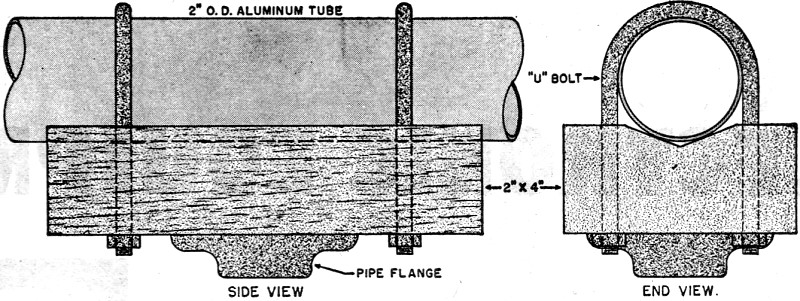
Fig. 5 - An ordinary two by four is used to mount the main frame assembly to the mast. Accordingly, it is to be noted in Fig. 1 that the dimensions for D 1, D 2, A and R, calculated from Table 1, are measured from the outer wall of the 2 inch tube frame to the element tip. The formulas give the dimensions for each quarter-wave section of each element, which is the measured distance from opposing sides of the tube frame to the tip of each corresponding quarter-wave element, or the distance which each quarter-wave element projects from the side of the frame. The total over-all cut length of the various quarter-wave sections, to permit adjustment from 28 to 30 mega-cycles, is: D1 & D2 = 8' 2" A = 8' 6 1/4" R = 9' 0" It will be obvious from this that this beam requires for the elements, 4 lengths of tubing 8' 8" long, 2 lengths 9' 0-1/4" long and 2 lengths 9' 6" long; for the frame, 1 length of larger o.d. tubing 12' long; and for the "T" section, 2 lengths of tubing the same diameter as the elements, 33" long. The additional lengths are to take care of the portion through the center section.
Fig. 6 - Two views of "T" section show mechanical details of construction. It will be appreciated that, by substituting a wooden supporting mast, this array may be oriented to give vertical polarization. Further, with the array in the horizontal position; the feed line may be carried parallel to the 2 inch tube frame either toward the front or the rear for any desired distance and dropped down from that point. In this application it is to be recommended that the feeders clear the tube frame by at least 3 to 4 inches. In connection with feeding beam arrays some controversy seems to exist as regards the delta match vs. the "T" or other matching systems. In considering the efficiency of a feeder system it may be stated that the energy lost is equal to the energy delivered to the sending end of the line minus the energy delivered at the load end of the line. At the lower frequencies, the energy loss consists mainly of the I2R losses in the line, which manifest themselves as an unusable form of radiant energy, namely heat. As the operating frequency is increased, however, another type of loss must be added to the I2R loss.
Posted July 19, 2022 |
|
")
 Design characteristics of a 4-element, close-spaced antenna array
featuring novel adjustable element length. Data applies to arrays for 28 mc. and up.
Design characteristics of a 4-element, close-spaced antenna array
featuring novel adjustable element length. Data applies to arrays for 28 mc. and up.