How to Interpret Standard Ratings for Meter Accuracy |
|
Even with the ubiquitous presence of affordable digital multimeters, there are still times when a meter sporting an analog movement is more useful than a numerical display. This is especially true is when a reading is varying about a mean value rather than being fixed. Sampling and display update times of digital meters can be too slow to realistically reflect what a time-varying signal is doing. An analog meter's pointer can more readily be followed than needing to read and mentally comprehend a rapidly changing numerical value. Digital meters are great for reading a fixed value or for precisely setting a fixed value, but tracing signals through a circuit with a digital meter can be very misleading because unless you are mainly interested in DC bias levels, the information presented can be misleading. In order to use an analog meter meaningfully, you really need to understand how the range chosen - be it voltage, current, power, or resistance - affects accuracy. This article does a great job of explaining why the scale selector should always be chosen such that the reading being indicated lie as close to full scale as possible - understanding this is extremely important! How many readers know the meaning of manufacturers' accuracy ratings, as applied to measuring instruments?
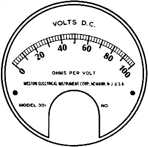
Figure 1 - DC volts meter face (0 - 100 V)
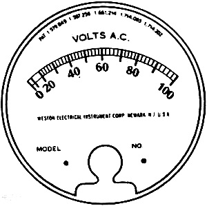
Figure 2 - AC volts meter face (0 - 100 V)
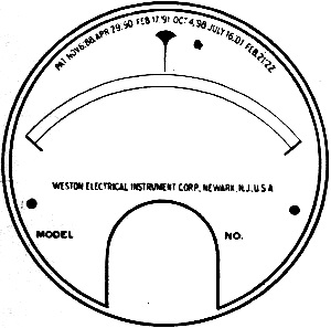
Figure 3 - Unmarked meter movement face
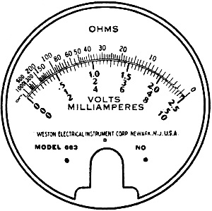
Figure 4 - Ohmmeter movement face (0 - ∞ Ω)
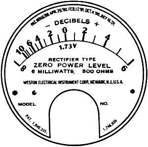
Figure 5 - Power meter movement face (0 - 6 mW)
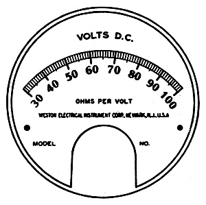
Figure 6 - DC volt meter movement face (30-100 V) Harold L. Olesen The accuracy of electrical indicating instruments and certain other devices as used in the radio service field, seems to be a subject that is generally misunderstood. Even though these units are rated by their manufacturers as being correct within a specified accuracy most users do not know how to apply this information advantageously. The instruments used in radio service practically all of the "indicating" class, as distinguished from instruments of the other classes, "integrating," "recording," etc. As a class, "indicating" instruments are treated as one group; the underlying principle regarding accuracy is the same for all. The length of the meter scale is the distance from the zero position to its other or full scale end, as measured along the arc traced by the tip of the pointer. This assumes that the zero position is at one end of the scale, which is generally the case. When the zero point is located at some mid-position on the scale, the pointer can move either to the right or left of it; the scale is then considered as having two end scale positions and the full scale length then becomes the sum of the distances from the zero point to each end scale position. The recognized standard for electrical measuring instruments in this country is that issued by the American Institute of Electrical Engineers. In this group of standards, Standard No. 33-33 covers the accuracy of indicating instruments. This standard reads as follows: "Accuracy of Indicating Instruments. - In specifying the accuracy of an indicating instrument; the limits of error at any point on the scale shall be expressed as a percentage of the full scale reading." Instruments whose scales are uniform, or reasonably so, and whose scale markings increase from zero at the point of zero indication to a maximum value at the other end of the scale fall in this group and are covered by the standard directly. This group includes all standard voltmeters, ammeters, and wattmeters for both a.c. and d.c. Figures 1 and 2 show typical scales of this group. In Figure 1 the scale is marked off into 50 uniform divisions which bear the identifying numerals 0-100. An accuracy rating of 2% on an instrument using this scale would mean that the pointer should indicate with an error not to exceed ±2 volts (2% of 100) at any point on the scale. Should the reading be made at the 100 mark, the maximum allowable error, ±2 volts would be 2% of the indicated value. However, if the reading should be made at 10 on the scale, the maximum allowable error, ±2 volts, would become 20% of the indicated value. For this reason greatest accuracy is obtained by properly choosing the ranges on indicating instruments of this sort so that large deflections of the pointer may be obtained. In Figure 2 the scale is marked off in units, so that the instrument to which this scale is attached may read directly in a.c. volts. Instrument practice considers this scale as having 50 divisions because each of the ten cardinal divisions contains 5 smaller divisions. The application of an accuracy rating to this instrument is made in exactly the same manner as in the case of Figure 1, except that the rating does not apply for the first 1/5th of the scale. The usable part of a scale of this nature is considered to be the upper 4/5ths and no attempt is made either to use the first 1/5th at the left-hand end of the scale, or to cover this portion of the scale with the accuracy rating. A reading made at the 100 point might be in error ±2 volts or 2% of the indication, but a reading at the 50 point might be in error ± volts, or 4% of the indication. The cramping present on this scale does not affect the application of the standard for accuracy. On instruments of this type it is obvious that deflections which carry the pointer into the open part of the scale are required for best accuracy. Special scale instruments in the group are those that: (a) are without divisions as such, (Figure 3); (b) are calibrated in secondary values, (Figure 4); (c) have their markings so distributed that zero and maximum readings do not coincide with the zero and maximum de-flection points, (Figure 5); (d) have a suppressed zero reading point, (Figure 6). This group requires a somewhat special interpretation of the accuracy rating standard. An examination of Figure 1 will show that as far as an evenly divided scale is concerned, there is no difference between an error expressed as a percent of full scale reading, and one expressed as the same percent of scale length. In either case the result is the same. Figure 3 shows a scale which has no divisions as such. The instrument on which this scale is used is one of many that are made to indicate when the circuit in question is properly adjusted to some definite value of voltage, current, or power. The length of this scale is twice the distance along the arc traced by the pointer tip from one end to the line at center scale. The instrument is calibrated at the mark shown on the scale, and hence the 2% tolerance applies at the mark and not as a percent of scale length or the reading that might be obtained at the full scale or end scale position. Figure 4 shows the scale of a typical series type ohmmeter. A true series type ohmmeter scale has but one arc, marked off in ohms. The scale shown in Figure 4 is that of a volt-ohmmeter and is taken from the Weston Model 663 volt-ohmmeter. This scale was chosen in order to have available a uniformly divided arc below the ohm arc, thus facilitating the explanation made below. It is obvious that, since the ohmmeter scale can be added to the face of an instrument already bearing a uniformly divided arc, the method of figuring the accuracy must be the same for both. In other words, the accuracy of the instrument is a function of pointer movement and is, therefore, independent of the type of scale used. Like the uniformly divided scale the ohmmeter accuracy can be expressed as a percent of scale length. In Figure 4 2% of the full scale range of the voltmeter becomes one division of the scale length. While this one division is always a fixed number of volts on the voltage scale, it is not a fixed number of ohms on the ohms scale, but depends on the location of the division along the arc. In Figure 4, 2% at the zero ohms position is equal to approximately .5 ohm. At center scale the maximum error may be equal to 2 ohms in 25, or 8%; at 1/5th scale 12 ohms in 100, or 12%. Here it is again apparent that the greatest accuracy is available when ranges are selected such that large deflections are obtained. An instrument having a 2% rating and using a scale as shown in Figure 5 would be considered as being within its guaranteed accuracy if the pointer indicated within plus or minus a distance equal to 2% of the scale length of the true value at any point on the scale. Figure 6 shows a suppressed zero scale which is also special as far as applying an accuracy rating is concerned. The zero deflection point of the instrument using this scale is suppressed by winding up the pointer spring equivalent to 30 volts deflection and permitting the left-hand pointer bumper to hold the pointer slightly to the left of the 30 volt mark when no current is flowing. Current through the instrument produced by the first 30 volts in the circuit under test is not indicated on the scale. The deflection of the pointer produced by the additional current through the instrument due to each additional volt between 30 and 100 volts is greater than would be the case if the scale and instrument were adjusted to read from 0-100 in the regular way. The accuracy of an instrument bearing a scale of this sort is taken as a percent of the top mark value indicated on the scale.
Posted December 9, 2021 |
|