Oscillators - How They Work |
|
National Radio Institute (NRI) was founded in 1914 at the dawn of the radio age. It provided self-study courses as well as classroom instruction on the art of electronics and radio communications. A bi-monthly magazine entitled National Radio News was published by them from 1929-1953. This article explaining how oscillators work appeared in the December 1940 edition. Although circuits of the day used vacuum tubes, the principle of voltage and phase relationships required to initiate and sustain oscillations are the same as for transistor circuits. A step-by-step description is provided from the time the power is applied until stable oscillations are established. More is known nowadays regarding actions at the atomic level regarding how oscillations begin, but the fundamental principles are the same. Oscillators - How They Work
J. A. Dowie, NRI Chief Instructor N. R. I. Chief Instructor In every radio transmitter, in every super-heterodyne receiver and in radio servicing equipment, we find oscillators producing the signal. It is this oscillator that supplies the signal that is so essential in carrying out our work. Since it is so important in radio, let's study in greater detail how it works. That is, how does an oscillator operate in generating the signal and how does it continue to develop a signal after placed into operation?Oscillator Circuits: There are a large number of different types of oscillators in operation. There are oscillators which maintain oscillation by the ionization of gas and by the projection of electrons through chambers where the rate of travel of the electron determines the frequency of oscillation. In this discussion I am going to cover only the operation of the better known oscillator circuits. The oscillators that are used most extensively in the radio field. For example, the tuned grid, the tuned plate, the Armstrong, the Meissner, the Hartley, the Colpitts, the ultraaudion, the push-push and the push-pull types with either the tuned grid or tuned plate or both. In my discussion I will cover these circuits and their operating characteristics. It will be pointed out, that when you understand the characteristics of oscillator circuits which depend upon capacitive or inductive feed-back that you will understand the operating characteristics of all of the conventional types of oscillator circuits mentioned above. Phase Relationship Between the A.C. Grid and the A.C. Plate Voltages: It can be stated that the primary requirement in order to sustain oscillations in either an inductive or a capacity feed-back circuit is that the applied grid to cathode voltage must be approximately 180 degrees out of phase with the plate to cathode voltage. This means that when the grid to cathode voltage is rising in a positive direction the plate to cathode voltage must be dropping in a negative direction. That is, the tube itself acts as an amplifier. Then, too, if the reversal is of a sine wave character the wave form of the signal generated will be a pure sine wave. Remember that the voltage applied to the grid of a tube which is not overloaded controls the plate circuit output wave form and that the triode tube is easily adopted to the inductive or capacitive feedback types of oscillating circuits. In an oscillatory circuit the tube does not become an oscillator - it continues to act as an amplifier - amplifying the voltage which is applied to its grid circuit and sending it through the circuit coupled to its plate. When the plate circuit is properly coupled to its respective grid circuit so that it continues to amplify the signal it excites itself, the circuit and the tube become an oscillator.
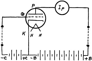
Figure 1A - Oscillator biasing.
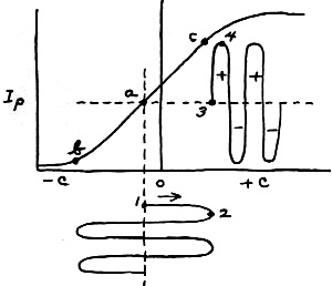
Figure 1B - Operating point. Since the tube continues to operate as an amplifier even though it is in an oscillatory circuit let us study some of the important characteristics of vacuum tube amplifiers. In Fig. 1A is shown a triode having electrode supply voltages. Its operating point being at a on the Eg-Ip characteristic curve shown at B. It can be shown that as the grid voltage of the tube is driven in a positive direction by some force that this will result in a decrease in plate voltage between P and K. This is due to the increase in plate current, the voltage drop being in the plate load and the polarity or phase of the voltage in this circuit being in a negative direction. Now when the grid is driven in a negative direction in the grid circuit the plate circuit voltage goes in a positive direction. This can be proven by Fig. 1B. Point 1 on the grid voltage moves positive to point 2 and the plate current increases from point 3 to point 4. An increase in plate current means a drop in plate to cathode voltage and from a high positive value to a less positive value with respect to the cathode. It is therefore evident that the voltage applied to the grid-cathode circuit must always be 180 degrees out of phase with the change taking place in the plate circuit of the tube in order to have the tube excite itself and thus maintain oscillation. So long as the signal voltage on the grid of the tube does not swing beyond points band c on the Eg-Ip curve there will be no wave form distortion introduced and if the coupling between the grid and plate circuit permits uniform wave form changes, then a sine wave will be developed in the plate circuit and consequently at the output of the oscillator. This condition of operation is known as class A amplification. Class Of Amplification: The efficiency of an oscillator is dependent to a large extent upon the class of operation. As in the case of the various classes of amplifiers used, the class A, Band C, the efficiency of the oscillator tube is the same as if it were an amplifier insofar as the tube is concerned. Figure 2 shows the relationship between the grid bias voltage, grid swing and plate current for the three fundamental types of amplifiers all of which may be used in the operation of an oscillator. Outstanding Amplifier Characteristics: The outstanding operating characteristics of a properly operated class A amplifier is the fact that the variations in excitation do not produce a change in the average D.C. plate current. That is, the increases in plate current are equal to the decreases and for this reason the average current taken from the power supply does not change. The grid excitation signal never drives the grid positive with respect to the cathode of the tube. In the class B amplifier increases in grid excitation produce proportional increases in the average D.C. plate current, that is, an increase in excitation raises the output of the oscillator. The grid excitation is sufficient to drive the grid positive but not off the straight portion of the Eg-Ip curve. The class C amplifier is operated so that further increases in grid excitation show no further increases in the average plate current. This condition of operation can only exist with the flow of grid current. The grid is driven positive and far enough to cause plate current saturation. It can also be stated that an oscillator employing a class C amplifier has very high harmonic content as the plate current exceeds the saturation point as can be seen at the upper right in Fig. 2. How Phase Relation Is Obtained: As stated there must always exist a 180 degree phase shift in the voltages between the grid and plate circuits in order to use a triode as an amplifier tube in an oscillator circuit. This required phase shift can be obtained by means of a transformer or through the aid of a phase shifting network or phase inverter consisting of another tube. Most oscillatory circuits use a transformer consisting of either one winding having a tap on it or two separate windings. For example, Fig. 3A shows a tapped transformer, often referred to as an auto-transformer. The position of the tap being selected to give the required excitation voltage for the class of amplification desired. The transformer winding gives us the desired phase shift because one end of the winding will always be of opposite polarity with respect to the other. No coil or winding on a transformer can have the same polarity when the winding is wound in one direction. One end will always be positive while the other is negative. This is the condition when all turns are linked together by the same electro-magnetic field. If we use an oscillator coil having two windings then the windings must be connected so that the grid end of one winding will be of opposite polarity with respect to the plate end of the other, thus keeping the 180° phase shift. The connections will be as shown in Fig. 3B.
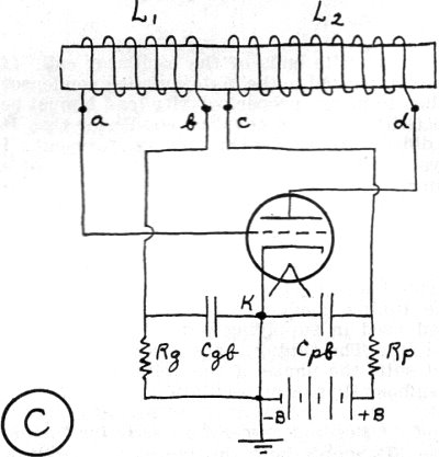
Fig. 2 - Relationship between grid bias voltage, grid swing and plate current for class A, class B and class C amplifiers. In class A, the grid never swings positive; in class B the grid swings positive only over the linear region of the plate current characteristic; in class C the grid swings beyond the plate current saturation point. How to Determine Coil Polarity: Oftentimes the serviceman is required to make an oscillator coil replacement and he is confronted with the job of connecting the unmarked leads of an oscillator coil to produce oscillations. In order to connect the coils of an oscillator so the phase will be correct, refer to Fig. 3B. Note that a and d are at opposite ends of the oscillator coil. If lead c is connected to the plate coupling condenser Ope then to insure proper polarity lead b must be connected to the grid coupling condenser Cgc. It isn't difficult to remember this requirement. I always say that when the grid is at one end of a coil form having two windings then the plate must be at the other end of the coil form when the two coils are wound in the same direction. That is, these two leads are always on the opposite ends of the two coils or at the two inside terminals. This rule holds good regardless of the placement of the tuning condenser or condensers or the method used in supplying power to the oscillator circuit. The tuning condenser or condensers do not shift the phase of the voltage across the coils sufficiently to stop oscillation. Method of Feeding Power to Oscillator Tubes: Figure 3B shows how the power or electrode voltages are supplied to the tube so it can amplify by what is known as the shunt or parallel feed method. The signal voltage generated is in parallel with the path taken by the power to the tube electrodes. In Fig. 3C the same circuit components are shown but connected to give us the series feed method of supplying power to the tube electrodes. Note that the coupling condensers are now by-pass condensers and are connected to the cathode of the tube. It is, of course, possible to use the series feed in the grid circuit and the parallel or shunt feed method in the plate circuit or shunt feed in the grid circuit and series feed in the plate circuit. The method of feed selected by the engineer in the construction of the device may be anyone of these combinations. The series plate feed method being somewhat more efficient than the shunt feed method as this method prevents Rp from shunting the plate circuit of the oscillator. Automatic C Bias Supply: Although the circuit shown in Fig. 3A has a C battery to enable class A operation of the tube at a given point on its Eg-Ip curve, it is possible to obtain class Band C operation by omitting the battery. This latter is possible because the upper end of the resistor Rg will become negative when the grid is driven positive by the excitation signal. The grid serves as the anode and the cathode of the tube as the cathode of a rectifier tube. The positive end of the resistor Rg being connected to the cathode. Rg may be considered the load on the rectifier. The voltage across Rg is dependent upon its current and resistance.
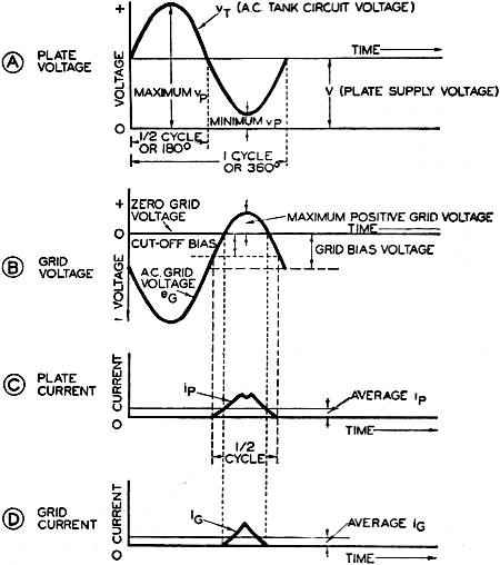
Fig. 3 - Inductive feedback Hartley type configuation. (A) C battery to enable class A operation, (B) B battery voltage is applied instantly, (C) Automatic C bias supply. How Oscillations Are Maintained: Now that we know how the proper polarity of the winding can be ascertained, how power may be fed to the tube and how the grid bias can be obtained automatically, let's determine how oscillations are developed and maintained. Assume that the cathode of the tube in Fig. 3B is at its operating temperature and that the B battery voltage is applied instantly. Upon application condenser Cpc will start to charge up to the value of the D.C. voltage dropped in the resistor Rp. Plate current will start to flow through winding L2. This causes a magnetic field to be present about coil L2. This field would appear to be of a steady value because the flow of the D.C. plate current is assumed to be constant. This is not, however, the case. The moment the plate voltage is applied the magnetic field about coil L2 starts to expand, which, according to the electro-magnetic law would link the coil L1, due to its inductive relation and would consequently induce an e.m.f. or a difference of potential across it. If then, the coils L1 and L2 are wound as stated above where coil L1 would produce a positive potential at the terminal a and a negative potential at b, the grid which is connected to a would receive a positive charge. This immediately partly neutralizes the space charge between the cathode and plate and allows more plate current to flow and at the same time causes the production of a negative grid bias. This causes a greater field to exist around coil L2 and results in a greater positive charge on the grid. The plate current then increases and in turn applies a greater positive potential to the grid. Of course this action continues until the plate current is limited by the emission characteristics of the tube or by the automatic C bias voltage which is developed by the rectified grid current which is across the resistor Rg. The turns ratio and amplification factor of the tube will also affect the peak value of plate current. When the peak plate current value has been reached, the magnetic field collapses and as a result the grid is driven negative. This causes a reduction in plate current which tends to aid in making the grid more negative. The grid may be driven so far negative that the plate current is completely cut off as shown in Fig. 4C. No further changes will then occur in the negative direction and again the magnetic field collapses. Then the complete cycle of operation will be reversed and as before the operation will start allover again. Thus it can be seen that the polarity of the coils L1 and L2 must be correct to cause the proper changes in plate current. Transformer Turns Ratio: It should also be evident that the greater the turns ratio of L1 to L2, the higher the voltage across terminals ab. That is, the voltage across winding L1 should be high and naturally the greater the number of turns in coil L1, the higher the voltage developed. This will mean more excitation voltage and also a greater plate current as more power will be required to supply the extra excitation. These facts also apply to the operation of the circuit shown in Fig. 3A and Fig. 3B. The turns ratio factor is also present and holds true when the inter-electrode capacity of the tube is used in tuning the entire circuit and when the tuning condenser is connected between terminals a and d in Figures 3A, Band C. When the tuning condenser is connected across either coils L1 or L2 then the coil without the condenser across it has the least number of turns. This is due to the fact that the condenser tunes the circuit to resonance and allows a higher voltage to exist across the coil and naturally with a larger magnetic field. Excitation Regulation: For a given plate supply voltage it is possible to find the correct excitation voltage by either selecting the proper number of turns or regulating the coupling or both in an oscillator circuit. The excitation voltage is also affected by the automatic bias voltage placed on the oscillator tube and the load coupled to the output circuit. For efficient operation of the oscillator circuit and for a given power output we must select the correct amount of excitation to give the class of operation consistent with the type of performance we desire. This value will usually be for the least amount of plate current that will give the most power output. There are other factors such as frequency stability and wave form that must be taken into consideration in the selection of the circuit values. It is the work of the radio engineer to select the proper operating characteristics of an oscillator circuit. Oscillator Output: The output of the oscillator is affected by a change in the oscillator plate voltage for a given turns ratio or coupling between the grid and plate circuits. It is also a fact that an increase in the D.C. plate voltage causes an increase in the D.C. plate current, the generated R.F. tank voltage, the R.F. tank current, the R.F. grid and plate current as well as the self-adjusting grid biasing voltage. These factors are all related to the power supplied to the oscillator for a fixed amount of coupling. It can also be stated that for a given supply voltage it is impossible to change any of the other currents or voltages in the oscillator circuit without changing all other values. This means that an increase in the coupling of the load to the oscillator circuit will affect all of the values of currents and voltages, that is, their relationship to the other values. General Discussion of Oscillator Characteristics: In discussing how oscillations are maintained we stated that the plate current increased to a value established by the emission characteristics of the tube. An oscillator tube functioning in this manner will not operate very long as it will lose its emission and become defective. It is for this reason desirable to provide a self-biasing resistor having a value of resistance which causes the production of the automatic C bias voltage that will give class B or C operation of the oscillator tube. Lower efficiency of operation is obtained when using either class B or A operation. The self-biasing grid voltage developed should limit the peak plate current rather than the emission characteristics of a tube in a well designed oscillator circuit. The ability for the self-bias voltage developed to limit the plate current flow is often referred to as a "braking action" that limits the grid A.C. voltages for a fixed amount of excitation and prevents them from reaching unsafe values of operation. I will add that if we get a clear picture of what takes place in an oscillator, the effects of changing any factor in the circuit can be explained very easily. Let us see what is the basic action in an oscillator circuit. When the oscillator reaches its final oscillating condition, we know that the grid is driven sufficiently positive to produce grid current which in turn develops across the grid resistor a definite negative C bias voltage. This voltage establishes a new operating point on the Eg-Ip characteristic curve. The A.C. grid voltage drives the grid positive and negative with respect to the operating C bias value as shown in Fig. 1B, always sufficiently positive so it creates this C bias voltage. The plate current flows only during that portion of the grid cycle when the grid voltage is less than the cut-off value. This is the point where the grid voltage stops the flow of plate current. The higher the excitation the smaller the operating angle for the plate current. For class B operation the operating angle for the plate current will be less than 180 degrees. In Fig. 4A and B we find the plate and grid voltage curves respectively. Note that the A.C. grid voltage decreases to a maximum while the A.C. tank circuit or plate voltage increases to a maximum. This is the correct phase relationship between the input and output voltages of a tube used in an oscillator. The plate current as shown in Fig. 4C and as ip pulse represents the driving power to sustain oscillations for it is this change in current that is fed back into the tank circuit to set this resonant circuit into natural oscillation. The area of this pulse when we view it as a graph represents available oscillating power, the greater the area of the plate current pulse the more the power available. Technically speaking any increase in peak current, any increase in the operating angle, and any trend to make the size of this pulse steeper and more flattened on top indicates more operating power for all of these factors increase the area of the plate current pulse ip. The amount of power consumed by the oscillator has a number of important functions to perform. It must overcome the losses in the tank circuit (resonant circuit), overcome the power lost in the grid resistor, the power lost in the grid-cathode of the tube, overcome the power dissipated in the plate-cathode circuit of the tube supply power to the load and any other incidental circuit losses as well as to develop enough excitation to drive the grid circuit of the tube in order to produce the correct amount of plate current.
Fig. 4 - These plate and grid currents and voltages represent operating conditions in the oscillator circuit of Fig. 3. Remember that graphs like these are always read from left to right. When comparing two voltages, that one which reaches a positive peak closest to the vertical reference line is said to lead the other; thus, νT in A leads eG in B. If we assume that there is a tendency for the A.C. grid voltage to increase then immediately the grid current increases and consequently the bias voltage becomes greater. This in turn reduces the operating angle of the plate current pulse, even though the current peak may tend to rise. Less power will then be available for oscillation and the braking action takes place preventing more power from reaching the circuit and consequently preventing the grid excitation to increase. If the grid A.C. voltage drops, the C biasing voltage is automatically reduced as the grid current is reduced and in turn the plate current flows over a greater portion of the cycle, resulting in the application of more power to overcome losses and again drive the grid up to a point where all losses are supplied and the grid excitation is sufficient to sustain the oscillating condition. The basic braking action is the inability of the oscillator circuit to draw enough power to take care of all current demands, and as a result the circuit sets itself to a definite operating condition and balance. For example, if we increase the grid resistor value from a low value to a slightly higher value the initial action results in an increased C bias voltage. As this takes place the operating point on the Eg-Ip curve of the tube is further negative. The grid, however, must draw current to supply automatic C bias voltage and to do this the A.C. grid excitation increases. Because of this grid circuit action the peak plate current goes up slightly but at the same time the operating angle decreases. The power drawn by the circuit depends on both the operating angle and the peak plate current. If we increase one and decrease the other by a small amount the circuit will draw more power increasing both the grid excitation and C bias voltage. Again the peak plate current increases but it is perfectly possible for the operating angle to decrease so much that the amount of power drawn starts to decrease at the point where maximum power is drawn from the supply balance occurs and the circuit conditions are stabilized. Of course we can make the grid resistor so high in its ohmic value that this condition of maximum power is far below any condition which would exist for normal circuit values, and a large grid resistor may actually produce less power in the oscillator circuit than normal low grid resistor values. Increasing the grid excitation using a given grid resistor may also decrease the power developed because the operating angle is decreased more than the peak increase in plate current. If we increase the D.C. plate voltage, the Eg-Ip characteristic instead of being held at the operating point as shown in Fig. 1B will move toward the operating point b. Therefore for an increase in plate voltage the grid current will be greater as the grid voltage is increased. and consequently a higher negative C bias will be produced as it will be required in order to cut off plate current, Since the grid A.C. voltage must always drive the grid positive to produce the automatic C bias voltage and as this C bias voltage is greater than the cut-off bias, the result is a much stronger current pulse; the plate current increases, as explained above. Under this condition more oscillating power is available and greater power will be received from the oscillator. With the usual testing instruments available to servicemen, only the D.C. plate voltage, the D.C. plate current and the self-biasing grid voltage can be measured with a voltmeter having a high resistance per volt rating. When there is any increase in the automatic D.C. grid voltage for a given value of grid resistance we have an indication of more A.C. tank voltage. This fact should be remembered and taken into consideration when servicing oscillators.
Posted March 24, 2022 |
|