Antenna Loading Problems and Solutions
|
|
Packard Bell was sold to a European company in the year 2000, and now markets PCs in the EU and Africa. Antenna Loading Problems and Solutions By J. T. Goode Asst. Chief Eng. Packard-Bell Co.
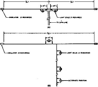
Anyone who loads a transmitting antenna for the first time soon finds out there is considerably more to the problem than what appears on the surface. The necessity of a proper match for transferring electrical power is a well established fact. Ways and means of accomplishing this result are numerous. To the engineer holding a college degree, the problem is purely mathematical. To the newcomer in radio, the problem is normally solved by an infinite number of experiments which result in a questionable answer. This same type of answer may be experienced by the engineer if he relies wholly on mathematics to create the proper match. When a transmitter is correctly matched to an antenna, the mathematical solution is achieved. Mathematical solutions to such problems deal with all circuits in a perfect state, which is seldom possible. Such being the case, the engineer must be in a position to decide where a compromise can be made in the effort to obtain perfection. The purpose of this article is to show short cuts with various r.f. loading problems. Many different types of low impedance transmission lines are now available. The first thing to keep in mind is that the proper impedance transmission line is required for different types of antennas. For instance, a folded dipole type antenna requires a 300-ohm transmission line for proper termination. The proper transmission line for a doublet antenna is 72 ohms. Assuming that the proper impedance transmission line has been selected for a particular antenna, the next step would be proper termination at the transmitter end. Commercially constructed pickup coils are now available with a known impedance. If such a coil is not used, the correct number of turns can be established by experimentation. Assuming the antenna is erected and the transmission line terminated on both ends to the best of your ability, the next move will be to make final adjustments and to determine that the adjustments are giving a maximum transfer of power from the transmitter to the antenna. Proper termination on the antenna end of the transmission line can only be obtained when the antenna length is a half wavelength at that particular frequency. When the transmitter frequency is shifted above or below this center point, a noticeable decrease in transmitter load will result. Antennas naturally take a maximum load at one frequency, so as the frequency is changed two things cause the antenna loading properties to decrease - mismatch of the transmission line and incorrect antenna length for the particular frequency. Although there are many methods of making final adjustments on an antenna, the author selects the following for reasons that can be readily understood, namely, economy and accuracy with a minimum amount of time and effort. The use of two sensitive r.f. microammeters is perfectly satisfactory for the following adjustments, but the meters require identical calibration. These meters are expensive and may be easily damaged with overloads. There is another r.f. indicator which, for this particular application, is equally as accurate as r.f. microammeters and costs 5¢ per indicator. The common panel light bulb meets this requirement. In case of an overload the expense of the damage will be the price of a light bulb. Installation of R.F. Indicators For example, let us assume that we are working with a transmitter with an input of 100 watts, and a frequency of 10 meters. Two wires are soldered to the connections of the light bulb base. These wires should be approximately six inches long. Two such light bulb assemblies are required. Refer to Fig. 1A for proper connection of light bulb assemblies to the antenna. Tuning Procedure Load the transmitter antenna by adjusting the pickup coil to the tank circuit of the final. Note brilliancy of light bulbs. Adjust antenna length for maximum brilliancy in each light. When this adjustment is correct, both light bulbs will be equal and at maximum brilliancy, indicating a maximum transfer of power from the transmitter to the antenna. If the impedance of the transmitter pickup coil is unknown, vary the number of turns so that maximum brilliancy of the light bulbs results. An antenna tuned by this procedure provides a maximum transfer of power from the transmitter to the antenna, which means that the best possible match for the particular application has been achieved. Under such conditions, the standing wave ratio on the transmission line is at a minimum. If such a condition does exist, the addition or subtraction of transmission line to the particular circuit will not affect the amount of power being transferred to the antenna other than the actual loss in the transmission line. Another method of indicating standing waves on a transmission line is to apply water to the transmission line and observe any change in the transmitter loading. A 72-ohm Amphenol flat transmission line is relatively unaffected during a rainy season if the line is free of standing waves. Placing r.f. ammeters in series with the transmission line will not give an accurate indication of maximum transfer of power to the antenna. A standing wave on the transmission line can cause excessive current to flow which would be indicated by the ammeter with a very small percentage of this power actually going into the antenna. If such a condition does exist, the loading of the transmitter can vary radically during a rainy season. It is possible to have a standing wave on a transmission line and still load the antenna with a fair degree of success. Such a condition exists when an untuned transmission line is cut to length resulting in optimum operating conditions. The number of amateurs that cut transmission line to obtain the proper transmitter load is surprising. If the light bulbs exceed their normal brilliancy during the tuning operation the length of wire to each bulb should be reduced equally. The light bulbs will then shunt a smaller portion of the antenna, resulting in less voltage being developed which reduces the brilliancy. For tuning applications, using low-powered transmitters, it may become necessary to use low current drain panel lights and shunt as much as 18" of the antenna. A 1-kilowatt transmitter will require approximately 4" of lead length for normal brilliancy. The light bulb method of tuning antennas can be adapted to practically any antenna. To prune an off-center-fed Hertz antenna, the following procedure should be used: Three lights bulbs are required, one at the center of the antenna, and two light bulbs shunting portions of the feeder. These two light bulbs on the feeder should be spaced approximately 10 feet apart. Refer to Fig. 1B. The antenna is connected to the transmitter and the transmitter turned on. The antenna length is then adjusted so that the light bulb in the center is at maximum brilliancy. The next adjustment is to slide the antenna feeder to different positions on the antenna so that both light bulbs on the feeder have the same brilliancy. If the light bulb on the antenna is at maximum brilliancy and the two light bulbs on the feeder are equal; the feeder is a non-resonant transmission line and the antenna is cut to the proper length. A final check is made by moving one of the feeder light bulbs approximately 4 feet. After this adjustment has been made, the two feeder light bulbs should remain equal in brilliancy. If there is a difference in brilliancy, the feeder will require additional adjustment at the antenna. Although the light bulbs make fine power output indicators as well as modulation indicators, it is recommended that they be removed after all adjustments have been made. If the neighbor's radio jumps off the table and these light bulbs light up at the same time, the neighbors undoubtedly will conclude that your transmitter had something to do with their particular problems.
Posted August 11, 2023 |
|


