The Aircraft Radio Serviceman |
|||||||||
Aircraft electronics has always been on the bleeding edge of technology because of the ever-increasing need to fly in the widest range of atmospheric conditions possible. Accordingly, skills needed by avionics servicemen are amongst the highest required in any electronics field. There are still many pieces of vintage equipment in service that need to be maintained, but even 20- to 30-year-old airborne radars and navigational units require top-notch techs to troubleshoot and align. One topic in particular that plagues electronics operation even in modern airframes is that of static electricity build-up and lightning strikes. We all face those kinds of static discharge hazards in non-aviation environments, but for the most part a failure on the ground or water is not as imminently life-threatening as a failure in the air. This article from a 1946 edition of Radio News does a good job of outlining issues that are still relevant today - maybe even more relevant with the replacement of relatively high-voltage-immune vacuum tubes with semiconductors. The Aircraft Radio Serviceman By Tony Wayne*
Irrespective of the modern trends of present day inventions, use of radio in light private planes doesn't seem to be popular. True, the war had a lot to do with it, but the war is over now. The principal reason for its unpopularity was, and is, installation and maintenance problems. Unlike the car radio, aircraft radio presents many problems, such as interference, bonding, electrolysis, and vibration. While most everyone drives a car today, and is familiar with its mechanics, this is not true of the airplane. True, most pilots are familiar with their planes, and possess a certain amount of the mechanical aptitude necessary; yet, relatively few servicemen know enough about aircraft to install this equipment properly. The experienced aircraft radio mechanics who were available prior to war, were absorbed by the airlines. Then too, the little aircraft radio business then existent was not sufficient to entice radio mechanics. This condition has been rectified largely during the past four years, as thousands of men have been trained in Armed Forces' radio schools.
The radio serviceman has always been a resourceful individual. When home sets were not coming into the shop fast enough, and competition was not only keen but rough, with radio shops in every block, in attics, basements, and bedrooms, the serviceman was repairing toasters, iron's, heaters, vacuum cleaners, and washing machines. With the advent of new radios, owners of old "blooper" or "orphan" sets, and recognized brands which have been holding out with a wire and a prayer, will be reluctant to have them repaired now. It scarcely seems the intelligent thing to do for servicemen to return to toasters and washing machines; rather, they should put their vast knowledge to work specializing in such fields as electronic equipment, television installation, small boat radio and aircraft radio maintenance and installation. There are a number of public airports for light planes springing up all over the country, and all of them are taking into consideration the varieties of services the private flyer will demand; and are building with the idea in mind of allocating various concessions necessary. Aircraft radio servicemen-this should be your cue - get your bid in now. These airports will furnish you the necessary space, either on a reasonable percentage or rental basis. All signs are definitely pointing toward an almost unbelievably rapid growth of the use of aircraft radio. Light plane purchasers can look forward to buying planes completely radio equipped. This is not mere crystal gazing, as many large light plane and radio manufacturers have made public this intention. The subject, in general, should become of interest to the radio serviceman. To meet possible demands for information concerning general description, installation, and maintenance of aircraft radio equipment, and some new and unusual accompanying problems, this article is written. Its purpose is to make available such pertinent information as will provide a general outline of aircraft radio; its parallelisms to the radio serviceman's present activities, showing that the slight departure from those activities will not be too radical. This article discusses the problems of aircraft radio, strictly from an elementary viewpoint, with sufficient detail given to enable the radio serviceman to answer questions intelligently. It is also intended that he will gain sufficient information from the detail herein so that he will be able to install and service aircraft radio. There are a number of factors met in servicing aircraft radio not common to average radio servicing. Mounting and installation alone are of great importance; and when servicing is done on the more complicated units, such as the automatic direction finder, automatic pilot, etc., need of experience and knowledge is greatly enhanced. Need for radio mechanics qualified to service aircraft radio will undoubtedly become greater in the near future, and the importance of sound and dependable training cannot be minimized. Aircraft pilot's dependence upon his radio equipment is too important to leave to the wiles of an untrained serviceman.
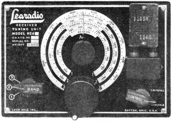
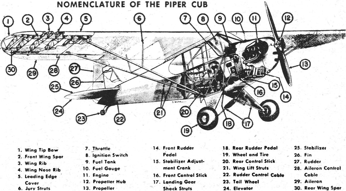
Before actually installing radio equipment, it is imperative that you understand the construction of light planes. For this purpose, we will use illustrations of one of the most popular light planes - the Piper Cub. These illustrations will give the necessary information concerning not only the Piper Cub, but many similar models as built by other manufacturers. Fig. 5 shows a cutaway view, clearly indicating the various parts of the airplane, together with their correct names. Recognition of these parts will enable you to talk "pilot's language" about any light plane. Fig. 3 shows the control system of the light plane. As a model for our aircraft radio discussion, we will use the model T-30, RCBB two-way aircraft radio equipment as manufactured by Lear, Incorporated. Front view of the receiver is shown in Fig. 1. To require a minimum of instrument panel control space, and to allow better weight distribution, this receiver has been divided electrically and mechanically into two units. The tuning control unit incorporates i.f. amplifier, detector, and oscillator; while Model G-3-AB unit contains dynamotor power supply, i.f. amplifier, second detector, a.f. amplifier, and range filter. In the case of the transmitter-receiver power supply, Model G-30-AB, the modulator unit of the T-30 transmitter is also built on this chassis; and it is only necessary to add the i.f. section of the transmitter and the necessary cables to have the T-30, RCBB two-way combination. A front view of the model T-30-AB transmitter tuning unit is shown in Fig. 2. The RCBB is a three band receiver covering the 200 to 400 kc. beacon band; the 500 to 1200 kc. broadcast band; and the 2800 to 6700 kc. aircraft communications band. Prior to the actual installation of any aircraft radio equipment, make a "bench" test of its operation. This will serve as a basis for trouble shooting the installation, should it not operate upon completion. Actual placement of the tuning control unit and the power supply in an aircraft installation is dictated by several considerations.
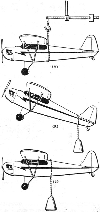
Whether the receiver tuning and control section is mounted in the instrument panel, overhead or elsewhere within arm's reach, must be determined by the user of the equipment and may be limited by space available in the instrument panel, vision, movement of controls or other considerations. The wide variety of individual demands and limitations imposed by previously installed equipment makes it difficult to recommend standard installations in aircraft already in use. Center of Gravity While an aircraft radio mechanic can scarcely be expected to be responsible for the weight and balance of the aircraft in which he is installing or servicing radio equipment, he should be concerned when his installation or the possible addition of radio equipment will affect the center-of-gravity consideration (Fig. 6A). Every particular airplane is designed to do a certain job and fly within stipulated load limits. The top limit is figured with a factor of safety sufficient to allow for stresses and strains of all ordinary operations. Attempting to fly an overloaded airplane will definitely decrease its range, increase its stalling speed, and require a longer runway to take off and land. Should an overloaded airplane run into rough weather or experience any other unforeseen trouble, the margin of safety due to high gross weight will be reduced to such an extent that the pilot may not pull through. Balance will affect an airplane's performance more than overload. An airplane slightly out of balance will not only change the spin and stall characteristics of the airplane, but will render it uncontrollable, and if a pilot encountered trouble in the air, he could not recover. - Fig. 6B. The center-of-gravity (CG) for a loaded airplane should be that point at which it would balance itself were it suspended, as shown in Fig. 6A. Vibration Shock and vibration are of relatively great amplitude and of three-dimensional character. The impact experienced when an airplane "bumps" in for a landing on rough terrain, is often of considerable magnitude and may cause serious damage to radio equipment if adequate cushioning of shocks is not afforded.
Also, it is important that radio equipment, in aircraft, be properly protected from the weather, as well as from such trouble makers as corrosion, commonly known as electrolysis. Two dissimilar metal bodies making contact with each other in salt air causes an electrolytic action to set in. This not only corrodes the parts, but results in a difference of potential, which causes noise in the radio. When installed in an instrument panel and when using rubber mounted brackets, sufficient clearance must be allowed in the size of the hole cut in the panel to prevent the receiver from vibrating and rubbing the instrument panel. Mount the receiver from the front of the panel. Mount the power unit wherever space is available - baggage compartment, cabin floor, or on a special mounting in the rear of the fuselage. Because the power unit need not be accessible for operation, it may be installed forward or aft in the fuselage to bring the center-of-gravity to a desired point. The various switches and controls may be installed wherever convenient and each cable to them should be securely taped and laced into place. Danger! Be certain that in lacing any electrical or mechanical cables they are not fastened to any of the aircraft controls. Double check all controls upon completion of the installation to be sure that they are free! Don't fasten the unshielded antenna lead parallel to any metal parts of the aircraft, such as the fuselage tubing, for a greater distance than necessary. The capacity between the antenna lead and such metal surfaces reduces signal strength. The antenna lead-in should not be shielded, except where transmission lines or coaxial cables are originally supplied. Don't run the antenna lead near any of the ship's ignition, or electrical wiring. This includes the primary of the ignition system to the ignition switch even though these leads themselves are shielded. Don't route the battery lead near the aircraft's magnetic compass. Check this by switching on the receiver and noting its effect on the magnetic compass. CAA and FCC Rules A mechanic installing radio equipment in aircraft need not be a certi-fied CAA mechanic. However, his work must be examined by one, to be sure it does not provide a hazard in plane operation. This is the only requirement in the Civil Air Regulations on this subject.
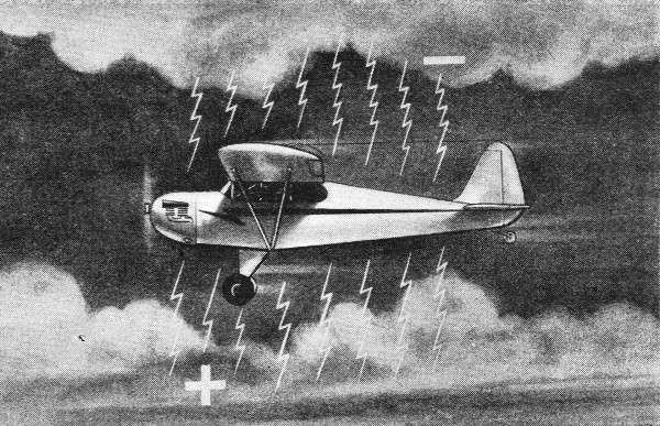
According to the CAA, " ... Anyone using an aircraft radio transmitter, whether in checking frequencies or contacting the tower, according to FCC rules, must have at least a Class 3 operator's license." The FCC has no specific requirements for radio mechanics performing work on aircraft radio equipment. However, personnel making adjustments to non-governmental radio transmitting equipment which involves the radiation of energy, should hold a radio operator's license of the second class or higher, either radio-telephone or telegraph. Now, the $64 question is - if it only takes a restricted phone ticket (3rd class phone), to operate the equipment in a plane, why make the poor mechanic take that "engineering course" - 2nd class phone or telegraph exam? Precipitation Static Aircraft radio servicemen should be cognizant of that type of static which is so common to aircraft radio-Precipitation Static - new pilots experiencing the brilliant fiery display on their prop tips, on the windshield, or along the wing and tail surfaces (as shown in Fig. 7), and have experienced the difficulties of the accompanying static, will expect the serviceman to do something about it. Actually, there is very little you can do, except give the customer an explanation of precipitation static, and then install a loop antenna, instructing the customer in its use. It has been discovered that certain types of aircraft antennas are definite sources of precipitation static, since the antenna is directly exposed to extremely high electric fields. These high fields cause corona discharge, which introduces electrical pulses directly into the radio receiver, shock exciting it, resulting in noisy precipitation static, Fig. 4. Some of the present day static dischargers are not successful in eliminating this interference at the antenna. More desirable methods are to use an insulating plastic covering on the antenna wire or to use a bare wire of a very large diameter. All metallic connections to the antenna and lead-in should be covered with an insulating dielectric material, preferably plastic. However, even these methods are not effective, since it is possible on first encounter with an electrical field of sufficient intensity, the insulation will be punctured and you will be right back where you started.
It has been common practice for quite a few pilots to reel out their trailing antenna, grounding it to some metal part of their airplane, in an effort to provide a discharge path for the charge. This is a waste of energy since the discharge noise is worse than that which the pilot is endeavoring to eliminate, and is especially dangerous in storm areas, as the trailing wire will function as a lightning rod, inviting lightning to strike and ruin the radio equipment. Bonding One of the primary requisites for noise-free reception is proper grounding or so-called bonding of individual units of an installation. Each unit should have an individual grounding strap securely fastened to the nearest metal part of the aircraft structure. When this structure is steel tubing, the plated copper braiding can be soldered directly to the tubing after paint is cleaned away. This operation requires a heavy-duty soldering iron and the connection should be cleaned off and repainted or shellacked to prevent corrosion or rust. Non-metal fuselage aircraft present a special problem in this respect, and the aircraft manufacturer should be consulted for the right method of bonding, if the usual method of bonding the motor mounts, the motor, and all metal braces, etc., does not prove adequate. It is important in any aircraft, that the primary, as well as the secondary of the ignition system be completely shielded. In some cases, control surfaces or moving metallic parts will produce noise in the receiver. Bonding of such offending points will usually eliminate this interference. Antennas Antenna selection is a matter controlled by the flight operations of the ship in which the radio equipment is to be installed. Generally speaking, the results obtained with various antennas are as follows: A whip antenna, while it gives the least signal pickup, does have the desirable characteristic for range or instrument flying of accurate and true radio range signals. It also gives a sharp "cone of silence" indication. The fixed antenna, mounted either overhead from the vertical stabilizer to a mounting or mast, forward on the top of the fuselage or the "belly" version mounted underneath the fuselage to another mast or to the landing gear struts, is called a "T" antenna when the lead-in is taken off the center. When the lead-in is taken from the forward end, this is known as the "L" antenna. When the receiver is mounted so that the antenna lead will be run nearly vertical to the "T" antenna, a truer range signal may be generally expected than with the "L" type. The signal pickup with both of these antennas is good. The trailing antenna, whether of the retractable reel or of the permanent trailing type, will give the maximum signal, and consequently should be used when trying to receive long distance or weak stations. The use of the trailing wire antenna, when an accurate range signal is desired, is dangerous. This is especially true when "close in" or "on instruments." It is feasible to have the benefits of all of the aforementioned antennas by the proper installation of a switching system. A suitable switch, or remote operated relays may be used for switching from whip to trailing. The selection of antennas on such a switching system should be clearly marked to prevent using the wrong antenna and possibly receiving erroneous range signals. It is desirable to mount the antenna so that the lead-in will be kept to a minimum. Insulated ignition wire (unshielded) makes good lead-in wire. Power Supplies Most aircraft radio equipment is operated from a 12-volt storage battery, with a generator being employed to charge the radio battery during periods in which the aircraft engine is in operation. Voltage regulators are used to maintain proper charging rate, as in the conventional automobile electrical systems. The open lead from the volume ontrol switch should be connected through a 10 ampere fuse to the nearest source of +12 volts. Most aircraft have a master switch or master fuse panel, with an additional fuse and connector provided for a radio circuit. All wire in this circuit should be number 14 or larger, copper stranded, and well insulated. Don't route this lead near any receiver antenna lead or near the magnetic compass. The shield of this lead is the negative return and should be securely fastened to the nearest metal portion of the ship's fuselage. Upon completion of installation, check the operation of the receiver and the dial calibration, with the ship's engine running. Failure to operate or improper performance means that the installation wiring must be checked. Refer to troubleshooting recommendations on page 30. Operation
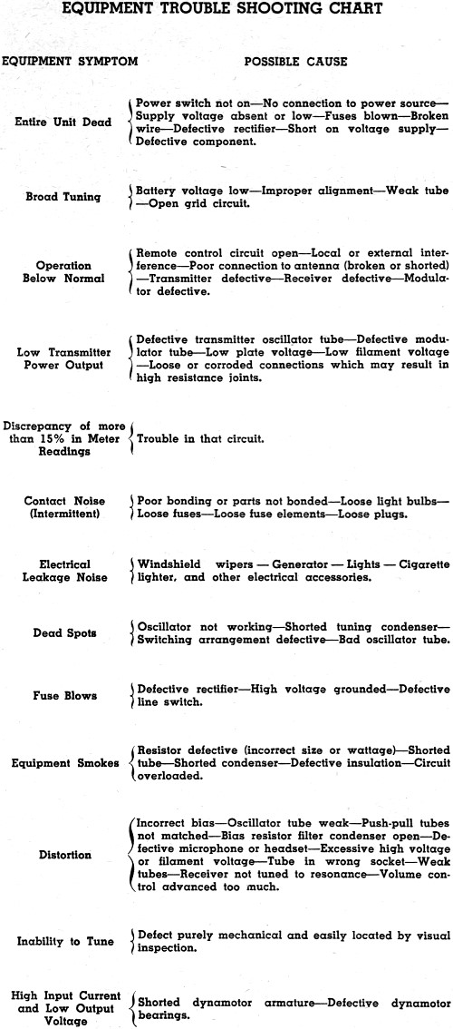
The on and off switch is incorporated in the receiver volume control and the battery power is supplied to the receiver through this switch. One or more pairs of low impedance (200 ohms) headphones may be used, plugging them into either of the two headphone jacks, which are connected electrically in parallel. The band selector switch is set to the number of the band to be tuned as indicated on the main tuning dial. Control tower reception is facilitated on band 1 by the 278 kcs. frequency being "spotted" on the dial. Sidetone connection is provided through a binding post on the power supply, permitting the pilot to monitor his transmissions over and above the receiver reception. Interphone communication is possible through the INT. connection on either of the power units. Code reception is possible by the use of the telephone-telegraph switch. Trouble Shooting Servicing, with the exception of the aircraft itself or mechanical troubles, should be done by competent radio service personnel having technical ability and the necessary test equipment to perform such service. Faulty operation should be localized in (1) the equipment, (2) attached accessories, such as headphones, antennas, etc., or (3) in the aircraft, its battery, the engine, or the installation. Trouble in the equipment itself should likewise be isolated in the following order - in power supply, audio and output section, second detector, intermediate frequency amplifier, or in radio frequency input section. Unless it is definitely known that radio frequency circuits are in need of realignment and the necessary test equipment and tools are at hand, "tinkering" with these circuits should not be tolerated. Shorted armatures are indicated by low output voltages and high input current. By disconnecting the output leads and running the dynamotor at its rated input voltage, if the input current of the G-3-AB dynamotor (without load) is in excess of 1.5 amperes, a shorted armature is usually indicated. Input current in excess of 3 amperes (without load) on the G-30-AB dynamotor is also the usual indication of a shorted armature. The armature should be removed and tested on a growler. Trouble shooting noise in aircraft equipment is difficult because of the many possible sources. Noises must be isolated, such as (1) in the equipment; (2) in the installation; (3) at the antenna, battery, or other accessories; (4) in the aircraft or its engines, or finally, (5) whether the interference is of non-man-made sources, such as the various static conditions encountered.
1. A good signal generator covering the range of frequencies used in the receiver. 2. An output meter, 0-50 milliwatts, 200 ohms impedance. 3. An insulated, non-metallic screwdriver for condenser trimmers. 4. A small metal screwdriver for r.f. coil core screws. 5. One 0.1 μfd., and one 100 μμfd. condensers. Alignment Procedure 1. Connect signal generator ground on output lead to receiver chassis ground. 2. Connect output meter in parallel with audio output. 3.Allow receiver and signal generator to "heat up" for accurate alignment. 4. Connect recommended dummy antenna condenser in series with signal generator output lead. 5. Before aligning, set dial pointer to small dot at low frequency end of dial scale when rotor plates of tuning condenser are closed. 6. Receiver volume set to maximum unless noise level is excessive. 7. Signal generator output set to limit receiver output to 50 milliwatts or less. 8. 30% modulation on signal generator output. 9. BFO switch set to "phone." 10. Sensitivity - 50 milliwatts output with 2 microvolts input; 4:1 signal-to-noise ratio. Maintenance The length of time between periodic maintenance checks on aircraft radio equipment will vary under the particular conditions of usage, i.e., temperature, humidity, and corrosive elements, etc. An arbitrary period of 200 actual-equipment-operating hours may be used, checking the following: Dynamotor When lubrication is needed, remove the end covers and bearing plates, clean with gasoline and apply enough Royco 6A grease (or equivalent) to cover bearings. Do not pack bearings. Keep grease off commutators. The dynamotor should be given a periodic visual inspection for armature shaft alignment; smooth, free-running bearings and end play in armature. The commutators, especially, should be inspected. Keep them clean by the use of "wet-or-dry" sandpaper. (Don't use emery cloth.) When commutators show signs of excessive wear, the armature should be removed and commutators "dressed." Brushes must be kept well seated and not allowed to wear so short that the spring pressure is insufficient. Any excessive sparking of the commutator should be investigated as to cause and the trouble then remedied. Relays All relays should be checked and kept clean and the contacts trimmed only when necessary. Fine sandpaper should be used on heavy duty relay contacts, followed by carbon tetra-chloride, to remove sand grit. When low current, small contact relays, are cleaned, special relay tools should be used whenever possible. Don't adjust relay arms and springs unless necessary. Dial Calibration While the user will usually detect any error in dial calibration, it is well to check it closely during any inspection. This should include mechanical inspection of pointer and knob, as well as circuit alignment check. The 278 kc. control tower spot on the dial should not be overlooked. Sensitivity When equipment is at hand, the receiver sensitivity should be checked and when low, proper service be effected. Field Etiquette The aircraft radio serviceman will find it necessary, on many occasions, to check frequencies with the control tower while he is working on a ship, either on the line, or in the parking area. He should familiarize himself with correct control tower and voice procedure. Avoid personal remarks or "rag chewing," and limit each transmission to strictly business. Don't use a normal tone when speaking into the microphone; raise your voice slightly and make pronunciation distinct. Knowledge of the standard phonetic alphabet is very useful. The control tower may, at times, find it necessary to resort to use of a signal light gun to flash you a warning or instructions. Learn to interpret signals properly and obey them, as your safety or that of someone else may be at stake. For the "wide awake" radio serviceman, the foregoing will serve to reaffirm his belief in the future-a future filled with opportunities and compensations. The era of the business lull being filled with toaster, washing machine, and vacuum cleaner fixing, is strictly passe. The radio serviceman is a bona fide member of the electronics fraternity, and as such, he should devote his time and energy to furthering his accomplishments there, leaving the maintenance of mechanical "household gadgets" to others. Installing and servicing radio aircraft equipment is vital to air travel, destined to become even more so in the future. Being in on the "ground floor," established at a field with a "future" and making it pay, will be the reward of those who are farsighted enough to reserve a "front seat center" for themselves, in the drama of tomorrow. Contrary to widespread opinion, installation and servicing of aircraft radio is not as complicated or intricate as it might seem. Although there are problems, such as precipitation static, bonding, electrolysis, vibration, and a few others encountered in servicing aircraft radio, there is not a great deal of difference between its installation and maintenance and that of the household radio receiver. Many radio servicemen have veered from familiarizing themselves with the aircraft radio field - why, we don't know, as it is definitely a lucrative field, and one in which every "go-getting" serviceman should become interested. Of course, all servicemen will not be interested in changing their clientele - either because they are firmly entrenched in household radio servicing, or because of other interests. However, we have endeavored to awaken and kindle an interest for this vital field by showing that it is not only a profitable, but a long-lived enterprise. Qualified radio men are needed now, and servicemen who have both sound and dependable training behind them should "climb on the bandwagon," in order to be assured of not "missing the boat" in the bumper field of electronics. The author is indebted to a number of individuals and organizations for assistance rendered in the preparation of this article. Mr. Henry J. Hamm, of Lear, Incorporated, made many of the photographs, circuit diagrams, and much of the data on aircraft radio equipment available. Thanks are also due Piper Aircraft Corporation for the use of photographs, diagrams, and data. *Formerly associated with the U. S. Navy Bureau of Aeronautics, and Aircraft Radio Laboratory. Wright Field. Dayton, Ohio.
Posted January 12, 2021 |
|||||||||