|
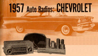
1957 Auto Radios: Chevrolet April 1957 Radio & TV News Article |
|
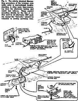
Apologies to Chrysler aficionados for not having similar articles for your classic automobiles, but this article from a 1957 edition of Radio & TV News magazine only covers Chevrolet radios (here is the equivalent report for 1957 Ford radios). Maybe someday I will acquire editions with other models. Transistors were fairly recent newcomers on the portable radio scene (on any radio scene for that matter), so you will please excuse the absence of them in most radios of the era. In fact, as evidenced by a companion article in this same edition titled "Delco's All-Transistor Auto Radio," such newfangled devices like transistors were reserved for top-of-the-line models like Cadillac's Eldorado Brougham. A move toward printed circuit boards, rather than the time-honored point-to-point wiring, was well underway, and push-button tuning was being sold to the car buying public as an indispensible safety feature - the "hands-free" feature of yesteryear. Even though push button tuning with memory (albeit mechanical) for storing station locations had been around for a long time in tabletop and floor model console home radios, miniaturization and added parts cost made them impractical for most automobiles. Take a look at the instructions for installation into and removal from the dashboard to get a good sense of how complicated everything has become. In 1957, disconnecting the car's battery did not automatically require an anti-theft unlocking code from the manufacturer to turn it on again. 1957 Auto Radios: Chevrolet Fig. 1 - The "Custom Deluxe Wonder-Bar," Model 987577 features push-button and search tuning, push-pull output, printed wiring, and a separate sub chassis for power supply and audio output. Transistors and printed wiring spark new design trends as streamlined tuning gains favor. With the right data, sets are accessible for service. While Detroit trumpets the design innovations in the line of chromium cruisers it is turning out this year to fill the nation's highways, often overlooked is the quiet revolution going on in the design of the radios on the sleek car dashboards. Trends are in evidence on at least four different fronts. Some attempts at finding new ways to put together an automotive receiver are in conflict with each other. Whichever way these conflicts are resolved, their very existence underscores the fact of change. The changes themselves, in any case, are of great interest both to the car owner and the technician who must keep these receivers in repair. The increased use of printed circuits, strongly evident, is not exclusive to auto receivers. The growing popularity of simplified station-selection devices, an occasional feature of household radios some years ago, is becoming the exclusive domain of the auto-radio designer - the man or woman behind the wheel can't always spare the hand needed for conventional manual tuning. Importance of the transistor - a "natural" in the auto radio, where the expense of its use can be balanced out against other savings it makes possible - has been responsible for at least two departures with conventional design philosophy, both aiming to accomplish the same thing. Choice of Receiver Types
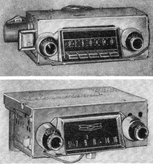
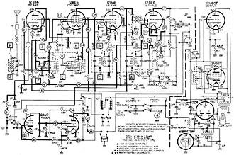
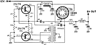
Model 987575 (upper) uses low-plate-potential tubes and transistor output. Model 987573 (lower) is a standard tube-vibrator unit. Of particular interest is the fact that no line can be drawn between one manufacturer and another in the matter of auto-radio design, at least in one important sense: we do not find that one manufacturer favors one type of approach, with a second manufacturer championing another radio design. Each maker has put the decision in the hands of the public by offering a wide choice of radios. For example, the Delco Radio Division of General Motors Corporation reflects in its 1957 line of radios the full gamut of innovation mentioned earlier. In fact, all the trends already noted plus at least one other, are evident in the choice of models available for Chevrolet cars alone. All of the Chevrolet receivers fall into the printed-wiring class. On some models, printed wiring is used throughout. On others, it is used throughout except for the power supply and audio-output portions, which appear on a separate subchassis, conventionally wired. One of the models with the separate subchassis is the "Custom Deluxe Wonder-Bar" set, Model 987577, shown in Fig. 1. Of special interest because it is the top model offered for the regular line of Chevrolet automobiles, Model 987577 sheds some interesting light on the present unsettled situation in design. With transistors making so much of the news, this top-line receiver incorporating all the deluxe features being offered this year is a conventional tube radio, as shown in Fig. 2. Until some trend definitely manifests itself as far as transistors are concerned, there appears to be a tendency to hedge with conventional receivers. Schematically, Model 987577 begins with the familiar lineup of r.f, amplifier, converter, i.f. amplifier, and detector-1st audio stages, all powered by a 12-volt vibrator supply, with gas-filled rectifier. Of special interest is the audio-output stage, in line with a generally increased awareness concerning audio fidelity. A push-pull output stage delivers up to 7.5 watts, which is quite a bit of power within the relatively small enclosed space of an automobile interior. The 6" by 9" oval speaker uses a high-energy magnet. While current audio practice generally makes use of a tube for a phase-inverter to feed a push-pull stage, note the transformer that fulfills this function in Fig. 2. Fig. 2 - Delco's "Custom Deluxe Wonder-Bar," Model 987577 (schematic), is the top receiver for regular 1957 Chevrolets. Although it provides push-pull audio output, search tuning, and push-button selection, it uses a conventional tube-vibrator circuit. The trigger circuit, in the lower left-hand corner of the schematic, operates a signal-seeking tuner mechanism, which it controls through a pair of solenoids (parts 106 and 107) and a relay (part 103). One of the solenoids returns the tuning cores to the low end of the band; the other is used to re-cock the power spring. Accuracy of the automatic tuning provided with this mechanism is reported as better than ±1 kc. Although the signal-seeking arrangement is electronically similar to that used in earlier versions, mechanical improvement has been achieved. Also, this tuner operates in conjunction with a mechanical push-button station selector, to provide the user with an unusual degree of flexibility in choosing his program material, whether he has a specific station in mind or wants to shop around the dial at random. Hybrid Design The "Custom Deluxe" receiver, Model 987575, provides push-button and manual tuning in a hybrid receiver that uses a single-unit chassis, featuring printed wiring. This increasingly familiar type of circuit, consisting of five tubes using low plate voltages and a single transistor, operates directly from the 12-volt auto battery without need of a vibrator or separate power supply. A prototype of this family of hybrid sets was described in an earlier issue of this magazine (see "No Vibrator in New Auto Sets," September, 1956, page 61, and "Low Plate-Potential Tubes," January, 1957, page 46). Generally speaking, Model 987575 follows the earlier hybrid prototype, with one change in tube type and another in the transistor type, although there are no changes in function. The r.f. and i.f. amplifiers are 12AF6's in this version, instead of 12AC6 as used in the other receiver. The converter is a 12AD6, and the detector-1st audio is a 12F8. To this point, the tube line-up differs from that in a conventional receiver only in that plate and screen voltages for these tubes are in the range of 10-12 volts. Following the 1st audio amplifier is a specially designed 12K5 audio driver. This serves to build up signal to provide sufficient drive for the input to the transistor. The output transistor is a 2N278 power unit. The 2N278, which is rated as a 14-watt dissipation unit at the usual 10 percent distortion figure, easily delivers the 6 watts of power output demanded of this stage. To maintain temperature control, the transistor is mounted directly to a cooling fin. This output stage is the only one which doesn't use printed wiring. Although the most elaborate receiver for the regular Chevrolet line is of conventional circuit design, the situation has been reversed with respect to the set used in the Chevrolet "Corvette." Here the same deluxe facilities - combined manual, signal-seeking, and push-button tuning, plus push-pull audio output - as provided in the "Custom Deluxe Wonder-Bar" radio have been included, but the design involves five completely conventional tube types, one rectifier (but no vibrator), and four transistors in an unusual configuration that parts company with the hybrid set using 12-volt tubes. Two of the four transistors in this receiver Model 3725156 comprise the push-pull audio output stage. There is no startling departure, in audio output, from what may be found in any number of 7-transistor portables now on the market, except for the above-average power output obtained. The two remaining transistors, however, are used as the heart of an unusual power supply. Fig. 3 - Two power transistors are operated as a blocking oscillator. Their output is stepped up through the transformer and rectified to provide "B+." Oscillator as Power Source The transistor power supply, which eliminates the need for the vibrator, is shown in Fig. 3. Input to this pair of 2N174 or 2N290 power transistors is the 12 volts supplied by the car battery. The transistors are in push-pull to form a blocking oscillator. In addition to the two windings, conventional to blocking-oscillator circuits, there is a step-up winding that feeds increased-voltage oscillator output to the plates of a full-wave rectifier. The filtered output makes available approximately 200 volts of "B+" for plates and screens of the conventional tubes. Readers may be reminded of the some-what related r.f. high-voltage power supplies in some early TV receivers. The push-pull audio-output transistors are the same type used in the Model 987575 receiver for the regular Chevrolet cars. In their class AB push-pull arrangement they provide approximately 11 watts of power output. The chassis consists of two sections: the r.f. portion uses printed wiring; the audio-power chassis section contains the four transistors and the 12X4 rectifier. The latter chassis section is made of heavy aluminum, and has the transistors mounted to it on mica insulators, In this way, heat generated by the transistors is conducted to the chassis through the mica to keep the transistors from exceeding their maximum junction temperature. Rounding out the Chevrolet line are two more conventionally designed units consisting of vibrator, rectifier, and five tubes (Model 987573) or six tubes (Model 987693). The five-tube set, known as the "Standard," is of straightforward design with conventional manual tuning. The second set, the "Custom Deluxe," adds an extra tube for push-pull audio output and provides for push-button station selection. Also, like the 987577, it uses two separately mounted subchasses - a printed-wiring r.f. unit and a conventionally wired section for the audio-output and power-supply stages. Fig. 4 - The strictly physical dismantling procedure of the average auto radio, prior to conventional troubleshooting. is often more time-consuming than the electronic testing and repair that follows. These explicit mounting details for the line of radios used in all Chevrolet 1957 models. except the "Corvette," should be valuable in saving servicing time. Servicing Roadblocks Car owners prone to reminiscence have been known to recall, with some amusement, the era when the still-novel auto radio was an intruder to the inside of the automobile, and looked it. The main portion of the radio would mount under the dashboard somewhere, in a separate, easily seen (and easily reached) container. The tuning head, often at the end of a separate extension cable, might be found on the steering wheel, roughly in the position that was occupied years later by the hand shift. While such arrangements scarcely made for streamlined appearance, they did provide the advantage of good access. In a matter of minutes, the entire radio could be taken out of the car and moved to a more convenient place for repair. In those days, the service Charge for repairing a defective auto radio was no greater than that for performing similar labor on a house receiver. Nowadays, radios must be built-in, giving the appearance of being part of the car. Accordingly, getting them out for service amounts to dismantling part of the car. On Chevrolet automobiles, as on many others, the best way to get to the radio is by way of the glove compartment. Removing this compartment provides clear access for one hand to one portion of the receiver, considerably simplifying the matter. For special considerations pertaining only to the regular line of Chevrolet cars, Fig. 4 will be found most useful. Its exploded views, called-out details, and pinpointing of differences for the choice of receivers available can save much time. Once the receivers are out of the car, troubleshooting routine becomes familiar. The speaker may be removed by loosening four nuts, not shown, located at each corner under the speaker grille. This permits the grille to be lifted off which, in turn, reveals the heads of four other screws, available from the top of the dashboard, that hold the speaker directly in place. Service technicians report that, difficult though the removal procedure would appear to be, trouble ends with the first effort. After one receiver has been removed from a given automobile, subsequent removals from the same make and year of auto present surprisingly few problems.
Posted May 23, 2023 |
|

