Servomechanisms ... How They Work
|
|
My introduction to servomechanisms was sometime in the early 1970s when I became aware of radio control (R/C) systems for model airplanes, cars, and boats. Modelers referred to them simply as servos. At the time, they were constructed with discrete electronic components crammed onto a two-sided printed circuit board with parts mounted vertically to save space, a brushed DC motor, and a feedback potentiometer. Cases were either metal or plastic, and the gears were plastic. Control / power cables had four or five wires. The servos in my first R/C system (OS Digitron 3-Channel) were 1-5/8" x 1-3/8" x 13/16", and weighed 1.7 oz. The 4-wire cable used a center tap in the battery to effect bias voltages for the transistor circuitry (-V/2, Neutral, and +V/2), and the fourth wire was the pulse position control signal. Modern servos with equivalent power are 1/8th the volume and weight, are faster, use integrated circuits, and have a 3-wire control cable. Of course there are also larger servos, but they are immensely more powerful, with most using metal gears and brushless motors. Servomechanisms ... How They Work
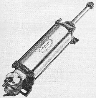
Bellows Air Motor is a typical servo-controlled device. Electronic circuits can control which way and how far an electric motor will turn or a piston will move By E. L. Safford, Jr.* Servomechanisms are electronic circuits that make electric motors run, open or close valves to control the amount of oil or air fed to a piston and serve in a myriad of other control and indicator applications. However, in this article we will deal only with motors and pistons that are connected to a load we want to move or position in some particular way. The electronic circuit we use may be nothing more than a potentiometer, a couple of relays and a tube or two. Or it may be an amplifier which is just as complex as hi-fi or public-address types. In audio work we want an amplifier to have little or no distortion. We also want plenty of power so we get excellent linearity when we operate at low power. And we want feedback to correct the response. An ac servo amplifier has about the same requirements. It must furnish enough power to drive a motor or valve. It must have a linear response over a range of very low frequencies since its input may be only a few cycles per second. It must also have feedback, but with servos this feedback is a little different. It must indicate the position or speed of the motor gear-train output shaft or piston shaft, and not be a portion of the signal being amplified.
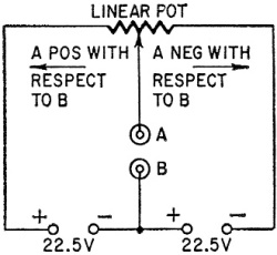
Fig. 1 - Linear potentiometer and two batteries form a balanced bridge.
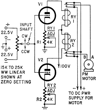
Fig. 2 - Simple motor-control circuit.
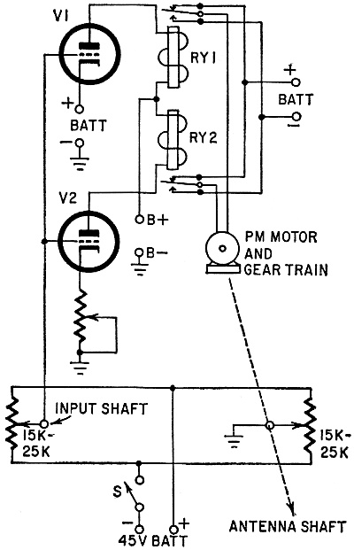
Fig. 3 - Motor-control circuit with a position feedback potentiometer.
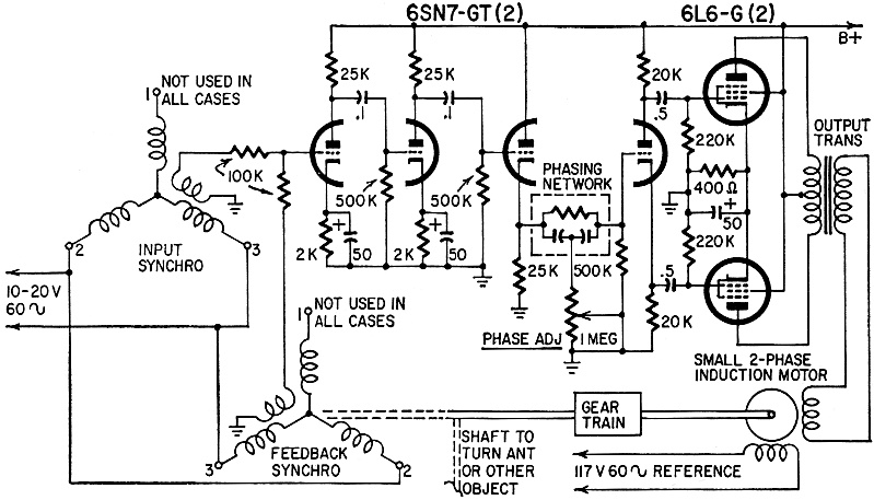
Fig. 4 - A representative ac servo.
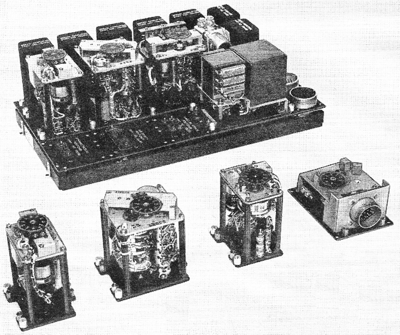
Eight servos are used in this Air Data Computer.
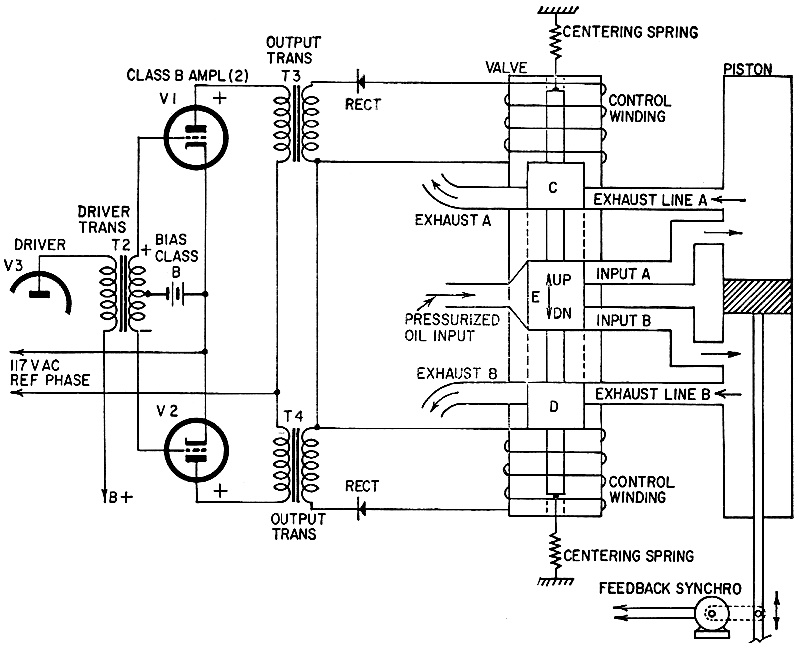
Fig. 5 - Representative hydraulic servo. The input signal to a servo amplifier must identify the direction we want the motor or piston output shaft to move in and tell it how far to move. We do this with a de signal by letting the polarity specify the direction and the amount of the voltage control the amount of movement. For an ac signal we let the phase, with respect to a reference voltage, tell the motor or piston which way to move, and again let the amount of voltage tell how far the output shaft is to be moved. Fig. 1 shows how a simple linear potentiometer can be connected to a pair of batteries to form a bridge circuit. When the wiper is in the center, the voltage across terminals A and B is zero. If the wiper is moved to the right, A becomes negative with respect to B. If the wiper is moved to the left, A becomes positive with respect to B. This could be an input circuit for a very simple motor control unit as shown in Fig. 2. We have not called this a servo, since it has no feedback. With the wiper centered as shown there is no voltage on the grids of the tubes. R1 is set so RY1 remains open. R2 is set so RY2 just closes. Since both motor leads are connected to the positive battery terminal, it does not run. Now we move the wiper clockwise. The bridge is unbalanced and a positive voltage is placed on the grids. V2 is not affected since it is already conducting and its relay remains energized. V1 starts to conduct and closes relay RY1. This connects motor lead A to the negative line. Lead B is connected to the positive supply so the motor runs clockwise. It will keep running till we move the wiper back to its center position. If we move the wiper counterclockwise, a negative voltage appears on the tube grids. V1 is unaffected (it is already cut off) but V2 stops conducting. This makes RY2 open and connect motor lead B to the negative line. Since motor lead A is connected to the positive supply, the motor runs counterclockwise. Again, it keeps running until we center the wiper. Position Control Fig. 3 shows how to add a second potentiometer, like the first, so it furnishes a position feedback signal to the tube grids. Now if we move the input wiper 10° clockwise, the motor output shaft also moves 10° clockwise and then stops. In other words, we can make the output shaft position correspond to the input shaft position at all times. This is basically what we want in any kind of positioning servomechanism. If we move the input wiper to the right, a positive voltage is applied to the tube grids. V1 conducts, closing RY1. The motor runs and turns the feedback wiper in the direction that brings it nearer the positive battery terminal. As soon as this wiper has moved the same distance from center that the input wiper was turned, the voltage difference between the two wipers is zero. The relay opens and the motor stops. If we center the input wiper again, it is nearer the negative battery terminal than the feedback wiper. Now a negative voltage with respect to ground appears on the tube grids, This makes V2 stop conducting, and RY2 opens. Now the motor runs in the opposite direction until the feedback wiper reaches the center position and no voltage difference exists. The motor would, of course, have a gear train between its shaft and the object we want to position. This may be a rotary antenna, a hydraulic valve, sonar transducer or any similar device. The feedback pot would be attached to the shaft the object is connected to. The AC Servo Fig. 4 reveals the similarity between an ordinary audio amplifier and a servo amplifier. The values shown are only indicative of those in use and not the exact values used in anyone amplifier. The idea here is to control the motion of a two-phase induction motor by controlling the phase to one winding. If we use a synchro transformer for the input, we can provide a 60-cycle signal which can be in phase or out-of-phase with the line voltage. We can control the amount of ac voltage to the input tube grid by how far we move the input shaft from its zero position. Note that we also have a feedback signal which will be provided by the same kind of device. The armature of the feedback synchro turns as the motor output shaft turns. Here is how it works: With input and feedback synchros properly set in position, there is no signal to the input tube grid. The motor has only its reference winding connected to the line and does not run. If we turn the input synchro shaft a little to the right, a 60-cycle signal appears on the tube grid. This is amplified, shifted in phase slightly (by the phasing network), amplified again by the power stages and applied to the second motor winding. The phase of this signal leads the reference by about 90° and the motor runs clockwise. As the motor runs, it turns the feed-back synchro and, if we have set it correctly, it will produce a signal exactly out of phase with the input. Thus when their voltages are the same, they cancel and the motor stops running since the amplifier no longer applies any voltage to it. The output shaft has been moved to the new position. If we move the input shaft back to its center position, its signal vanishes. The signal now applied to the input tube is from the feedback synchro and is 180° out of phase with the one we used a moment ago. When this signal is amplified and fed to the motor winding, it is a voltage whose phase is lagging the reference. Thus the motor runs in the direction that moves the feedback synchro armature back to its zero position. The motor stops when the signal to the input tube vanishes. The Hydraulic System Fig. 5 shows the basic elements of an electrohydraulic servo system. Examine the valve-piston arrangement first. The valve consists of a rod with three metal wheel-like sections fastened or cut as a part of it - C, D, and E. The rod is held in place in the metal block by two centering springs. It can move up or down like a solenoid when either winding has current flowing through it. Note that, as shown, the center part, E exactly covers the input hole where a pump, for example, is trying to force oil into the valve. C and D exactly cover the two exhaust lines so that oil in the piston cylinder cannot get out. Now suppose the upper winding is energized, pulling the rod up. E opens the input line from the pump and also opens input B to the piston. Oil flows into the bottom of the cylinder and cannot get out since D still covers exhaust line B. However, part C has uncovered exhaust line A and, as the oil flows into the bottom of the piston, the piston moves up, forcing oil from the top part of its cylinder out through exhaust line A. When the piston has moved enough to turn the feedback synchro enough to cancel the input signal, current to the top winding stops. The valve re-centers and the piston stops moving. This same action takes place if the bottom winding is energized and the piston will move in the opposite direction. Now let's see how we can energize one winding or the other by changing the phase of the input signal as we did with. the ac servo. A new output stage is required. The rest of the amplifier is the same as in Fig. 4 except that the cathode follower and phase inverter are replaced by V3 and transformer T2 of Fig. 5. VI and V2 in Fig. 5 are biased class-B and 117 volts ac is applied to their plates. T3 and T4 are small separate transformers. Here's how these work: Since V 1 and V2 are biased class-B, normally no current flows in either output transformer. If we apply an input signal which is in phase with the plate reference, making V1's grid positive at the same time as its plate, V1 conducts. The signal goes through T3, is rectified and causes a current to flow in the upper valve winding. V2 does not conduct with this signal because when its plate is positive, the grid is negative and, when its grid is positive, its plate is negative. When we change the phase of the input signal by 180°, V1 does not con-duct but V2 will, since now its grid will be positive when its plate is. The lower valve winding will now receive current. Remember, only two basic servo types have been discussed. There are many others. Some of them will be described in future issues. * Author: Model Radio Control, Gernsback Library.
Posted July 14, 2023 |
|