How Relays Work
|
|
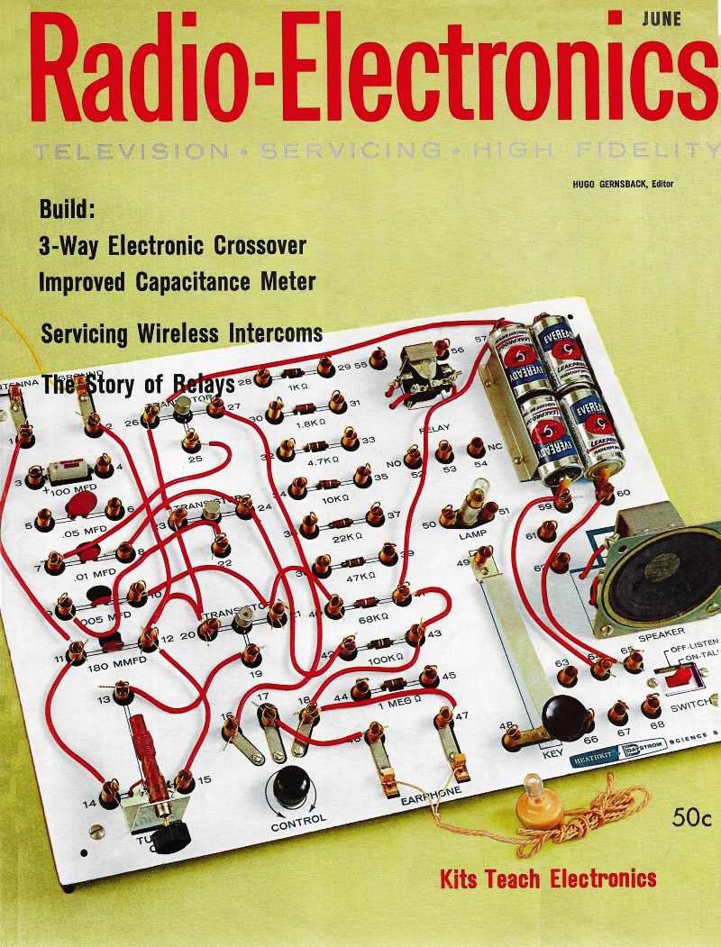
Even back in 1961 when this "How Relays Work" article appeared in Radio-Electronics magazine, there was a large variety of electromechanical relay types. Many of those have been supplemented or replaced by solid state equivalents, but there are still some applications where only good old hard physical contacts can do the job for both practical and economic reasons. Very high temperatures and systems with no electronic interface are examples. One very common example of the latter is the contacts that a centrifugal switch uses to take the starter capacitor of single-phase induction motor in and out of the circuit. The main diagram shows a clapper relay, a meter relay, an induction relay, a thermal relay, reed relay, and a piezoelectric relay, among others. In the days before everything being controlled by solid state devices, amazing electromechanical contraptions were designed to perform actions according to mathematical equations describing physics principles. Gun turrets on ships, airplanes, and tanks are significant examples of target tracking and motion compensation used in fire-control systems which incorporated many relays. How Relays Work: Part I - A close look at clapper, solenoid, induction, thermal, stepping and reed type relays
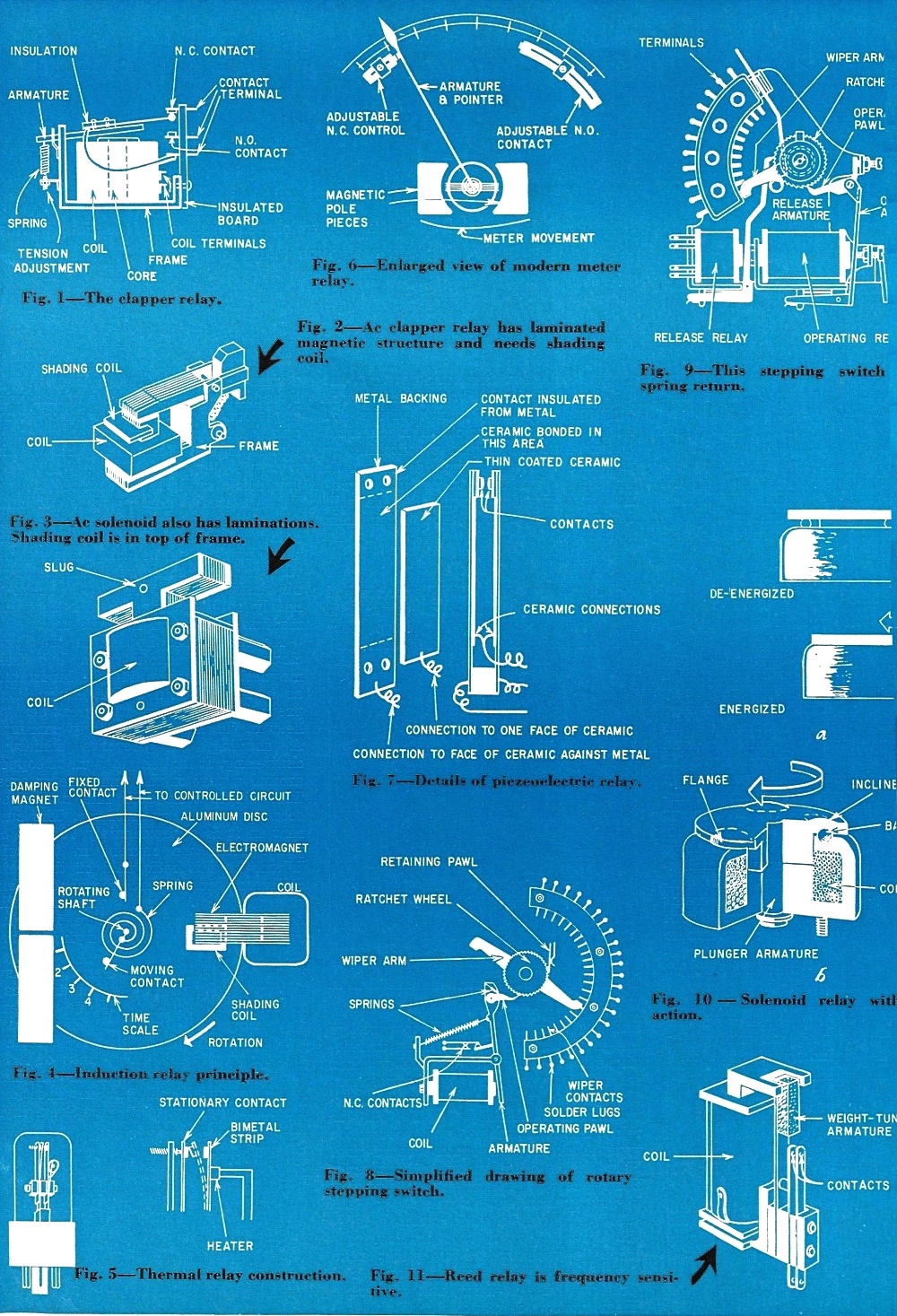
Relay Operation Fig. 1 through Fig. 11 By Tom Jaski The electronic technician who plans to go into industrial electronics should put relays high on his list of must-know subjects. In industry, all control was handled by relays before electronics came along. Even now the majority of industrial control circuits use relays in many forms. With electronic controls, many relays have to be used, and often the technician meets strange-looking devices that don't appear to be relays but are. Let's see how relays began. In 1824, an Englishman named Sturgeon invented the electromagnet. In 1829, Joseph Henry, professor of mathematics and natural science at Albany Academy, added an armature which carried contacts, and thus the relay was born. In dc circuits, relay design has changed, mostly because of the necessity for mass production and adaptability. But Henry's principle has never been improved upon very much. In 1886, alternating-current transmission was inaugurated. Where relays were needed, modified dc units served. Then development of special ac relays began, and there were so many contributions in that period that most contributors will probably not get credit for their work. In 1901, Westinghouse introduced the induction relay. These are very common, and are very important in our giant power distribution and transmission systems. Only in the last few years have new principles been applied to relay service. These principles were made available by materials technology in the electronics industry. One such development is the Mullenbach Capaswitch, which uses piezoelectric characteristics of artificial materials to obtain mechanical motion. But in contrast to switching by nonmoving devices, such as magnetic amplifiers, vacuum tubes and transistors, relays as discussed here still depend on mechanical motion for their function. Classes of Relays Relays can be classified by the method used to translate electrical power into mechanical motion. Thus for dc there are the clapper (the most common) and the solenoid type. Clapper relays are most familiar in the form of telephone relays, small control relays used in model control and similar applications. Fig. 1 shows the basic construction of a clapper relay. Another clapper relay, not as common, is the horseshoe type used in pipe-organ construction. This one is reminiscent of the early Henry relays, except for refinements in construction and materials.
Solenoids are a special class of relays.
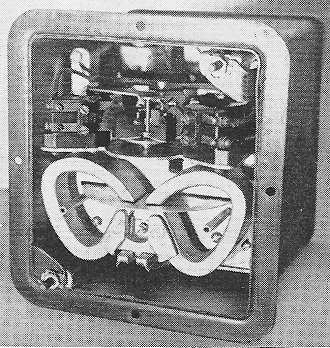
G-E induction relay. The solenoid relay, in which a movable core is used to open or close contacts, is used where we must take advantage of the greater travel and force available in them, and where the linear motion is particularly suitable for control of the relay characteristics. For example, it is very simple to make a time-delay relay from a solenoid type by adding a dashpot - a cylinder with a piston. The amount of force it requires for motion depends on what the piston moves. Sometimes this is air, which is allowed to leak out through a small hole controlled by a needle valve. With a steady force on the piston it takes time to move it, and a time delay is obtained. Initially, the air in the cylinder can be compressed somewhat, and the time characteristic of an air dash pot is. not linear. To make it nearly so, a noncompressible resisting medium such as oil must be used. Ac relays also appear in the basic clapper and solenoid types, but their magnetic structure must be laminated, as in Figs. 2 and 3. The laminations prevent the creation of a great deal of heat in the iron due to eddy currents. A shading coil prevents armature chattering. It is a single turn of copper around a part of the armature or core. This single turn acts like a shorted secondary on a transformer. The current in it is approximately 90° out of phase from the current in the coil. When the magnetic field of the main coil goes through zero, the shaded portion of the core still has some magnetic field, keeping the armature in place against the spring force trying to remove it. The next most prevalent ac relay (although not used in communications) is the induction type. Many of them appear in industry where they protect large generators and motors, compare the current in the three lines of a 3-phase system, and determine whether it is flowing in the proper direction. Practically all types of induction relays incorporate some time delay, often inversely proportional to the current. This is one of the reasons for their adoption in the first place; their operation depends on a motor action which takes some time. Fig. 4 shows the principle of the induction relay. It is akin to the watt-hour meter that measures power consumption in every home. It consists of a disc (usually aluminum) mounted on a rotating shaft. The disc rotates between the poles of a shaded electromagnet and a permanent magnet. Eddy currents induced in the disc by the main portion of the electromagnet pole are in phase with the currents in this coil, but out of phase with those in the shaded pole piece. As a result, the eddy currents generate a magnetic field out of phase with the shaded pole field, which "pushes" against one side of this field and causes the disc to rotate. The permanent magnet slows down the disc. The moving disc section between the permanent-magnet poles has currents induced in it in such a way that the magnetic field from these currents opposes the motion that created them. This is an application of Lenz's law. The spring retains the disc until the current is strong enough to move it, and returns it to its starting position after the current subsides. The unit shown in Fig. 4 is a very elementary induction relay with a somewhat peculiar time-current curve. To get the much used inverse time-current characteristic, a complicated magnet structure is designed for the driving electromagnet, with several coils above and below the disc. The explanation of this type of relay action is too complicated for a brief discussion and falls outside the scope of this article. Strange Breeds
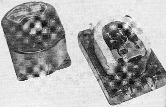
Early Weston meter relay.
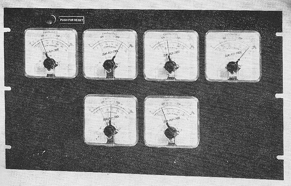
Panel of six meter relays.
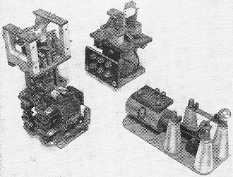
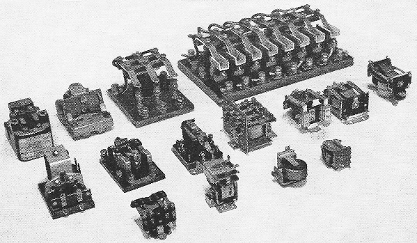
Clapper relays come in assorted sizes and shapes. Special relays come in many forms. Most familiar, perhaps, is the thermal relay using a bi-metal strip to operate contacts. These are quite frequently employed in radio transmitters to delay the application of B-plus voltage until filaments are heated (Fig. 5). Another special relay, used where sensitivity is of paramount importance, is the so-called meter relay (Fig. 6). It consists of a D'Arsonval type meter movement, with a pointer. The pointer carries very small contacts that close a circuit when the pointer is deflected a preset amount. Sensitivity is adjusted by setting the "fixed" contacts in a particular position. They can be moved with a small screwdriver or a knob on the instrument. In modern versions of the meter relay, the contacts are no longer on the pointer but on a special yoke and the pointer acts only as an indicator. A recent type of relay is the piezoelectric. It uses a barium titanate slab which deforms when voltage is applied to electrodes on its surface. The distortion is used to close contacts (Fig. 7). Stepping Relays Ratchet or stepping relays are special applications of the clapper type. Through a pawl-and-ratchet arrangement the armature moves a shaft that carries a cam which opens and closes contacts in sequence. Stepping switches are an extension of this idea. In these units the armature also rotates a shaft through a pawl and ratchet, but the shaft carries wipers which make contact with a large number of stationary contacts successively. Figs. 8 and 9 show two kinds of stepping switches. The one in Fig. 8 rotates continuously, stepping one notch each time the relay coil is energized. The switch in Fig. 9 steps a certain number of times and then is returned by the release armature, which lifts the pawl, allowing a spring to return the wipers to their starting position. An unusual relay is the rotary solenoid type shown in Fig. 10. Here the core is drawn into the solenoid. Attached to the core is a disc, which is held by a spring. The disc rides on ball bearings that ride in inclined grooves on the frame. As the core is attracted deeper into the coil, a force is exerted on the disc, pulling it down toward the solenoid coil. The only way it can get closer is by rolling the ball bearings down the inclined grooves, thus rotating the disc. The shaft of the rotary solenoid can carry contacts, cams or the rotating wiper section of a wafer switch. Last, there are frequency-sensitive reed relays. In these units the armature is a tightly clamped "tongue" similar to the little tongues in a harmonica (Fig. 11). The tongue has a natural resonant frequency. If the coil carries ac of this frequency, the tongue vibrates. The end of the tongue or reed carries a contact which closes many times per second when the reed vibrates. A slow-opening auxiliary relay is kept closed by this periodic contact until the reed stops vibrating. Obviously, one coil can carry many reeds, all responding to different frequencies. This basically is the entire array of relays available. There are many special versions of these basic types, and some unusual devices which could also technically be called relays (some of them pneumatic-electric), but in principle they are all the same. To Be Continued
Posted July 31, 2023 |
|