Mr. Math Analog Computer |
|
Back in the early 1990s, while working for a fine Midwestern company that made automated utility meter reading (AMR) equipment, an older gentleman was hired as a contractor to do some design work. He was an instant hit with everyone not just because of his engineering prowess, but because of his stories of the mechanical and analog electronic computers he worked on for the U.S. Navy. After being commissioned as an ensign at the U.S. Naval Academy in Annapolis, Maryland, he spent time studying, researching, and designing massive radar-directed gun pointing systems for battleships. Just as contraptions like Babbage's difference engine was a marvel of contemporary engineering, so, too, were those fantastic shipboard amalgamations of gears, switches, vacuum tubes, rheostats, flywheels, cams, and bearings. Calculations of azimuths and elevations were made using sum, difference, integrating, and multiplication circuits built of discrete analog components and electronic valves (...for the Brits who might be reading this). If you ever have the opportunity to tour a WWII era battleship (I have been on the USS North Carolina in Wilmington, NC), be sure to go below and view the inner workings. This article from a 1958 (the year I was born) edition of Radio-Electronics provides a little insight into the workings of an analog calculator. BTW, the old Navy salt was, according to the chief engineer at that AMR company, the only person he ever interviewed who was able to correctly answer every question asked (yes, I failed a couple during my interview). See also The Convair Analogue Computer. Mr. Math Analog Computer By Forrest H. Frantz, Sr.
Mr. Math ready for use. Simple electronic computer adds, subtracts, divides and multiplies Industry spends millions of dollars each year for computing instruments to free engineers, technicians and office workers from the labor of doing long computations by hand. Time that was spent doing this work is now used in more creative and productive pursuits. Can this work for you as a service technician, ham, hi-fi enthusiast or experimenter? Yes, it can! With a modest calculator you can enjoy these benefits on a smaller scale. Mr. Math is just such an instrument. It will help you make accurate calculations for most electronic and electrical problems. Mr. Math opens the door to analog computing for you. You'll find math less laborious and more interesting. Your understanding and ability to use it advantageously will increase as you use Mr. Math. What Mr. Math can do What can you expect from Mr. Math in problem ability and accuracy? Ability: Mr. Math can be used to work problems involving these commonly encountered formulas: E = IR, I = E/R, R = E/I, P = E2/R, P = I2R, e = Emsin θ, e = Emcos θ, XL = 2πfL, XC = 1/(2πfC), Z = √(R2+ X2) tan θ = X/R, cos θ = R/Z, sin θ = X/Z, X = R tan θ, X = Z sin θ, R = Z cos θ, Gain = Eout/Ein, Gain = μZL / (rp + ZL), μ = gmrp, fo = 1/ [(2π√(LC)] and others. Accuracy: 1% is usually considered adequate for engineering purposes. Mr. Math is accurate within 1% when carefully constructed, calibrated and used for most problems. With average construction, calibration and use, Mr. Math's error will be less than 3%. Here's how Mr. Math is used:
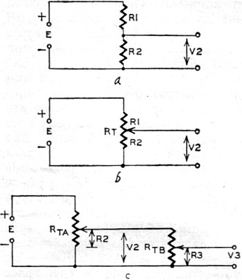
Fig. 1 - Basic system of generating numbers and multiplying with cascaded potentiometers.
Fig. 2 - Electronic adding with a mixing circuit. Problem: You're fixing an old ac-dc radio that has a burned-out series-heater resistor. The total drop across the tubes must be 68 volts at 0.3 ampere. The line voltage is usually 120 in your locality. What should the resistance of the replacement be and how much power will it have to dissipate? All you do to solve the problem is set four dials to obtain the resistance in ohms and readjust two of them to obtain the power in watts that the resistor will dissipate. Simple, isn't it? Mr. Math's circuit is simple, but, before you become too involved with it, glance at Fig. 1-a. A battery of voltage E is connected to series resistors R1 and R2. In a series circuit, the current through each resistance is the same and the sum of the voltage drops across the resistances is equal to the battery voltage. Therefore, V2 = I R2. And, if R1 plus R2 equals 1,000 ohms and R2 equals 200 ohms when E is 10 volts, V2 will be 2 volts. Thus, V2/E equals 0.2. If resistances R1 and R2 of Fig. 1-a are replaced by a potentiometer as shown in Fig. 1-b, voltage V2 may be varied by rotating the pot's shaft. R1 plus R2 is constant and is equal to the potentiometer's total resistance. R2 is equal to the percentage of shaft rotation times total resistance. Total mechanical rotation possible with the potentiometers used in Mr. Math is 300°. But, the metal connector tabs on the ends of the resistance element take up 10° each. Therefore, the electrical rotation is only 280° So a 28° rotation of the shaft corresponds to a 10% rotation, and V2 will increase by 10% of E. If the potentiometer has a scale with ten 28° divisions, each marked from 0 to 10, and E is 10 volts, a pointer knob on the potentiometer will indicate the magnitude of V2 directly in volts. Thus we've generated the numbers between 0 and 10. How can we multiply? With a little thought, you will see that we already know one way to multiply. In Fig. 1-b we multiplied E by numbers between 0 and 1 and, when E equaled 10, generated the numbers between 0 and 10. This was done when the potentiometer input voltage was constant. If we add a second potentiometer with its outer terminals across V2 as shown in Fig. 1-c, we can multiply V2 by another number between 0 and 1. We can calibrate RTB from 0 to 10 if we. wish and increase E to 100 volts. Thus, with RTB and RTA set to 10, we have 10 x 10 = 100. However, there's no need to let the number 1 equal 1 volt. If we let it equal .01 volt, we can let E equal 1 volt and still graduate the potentiometers from 0 to 10. Thus, for 2 x 4, V3 equals .08 volt, or 8 units. A voltmeter with the proper range could be calibrated to read directly in units from 0 to 10, and the meter range switch could be calibrated in multiples of 10. To make the multiplication method of Fig. 1-c work properly, RTB's resistance should be at least 10 times RTA if you want to use linear scales. Even then, there'll be some error (approaching 2% maximum) if you try to use linear scales. Furthermore, to multiply more than two-digit numbers with a string of cascaded pots, you run into the problems of using a large input voltage, a very low resistance for the first potentiometer to get a reasonably low resistance for the last pot and a very-high-sensitivity meter for answer read-out. Another disadvantage is that you cannot divide unless you provide a reciprocal scale (difficult to make and use) and multiply to divide. Thus, 3 divided by 7 would be 3 times 1/7. But, there's another way to multiply and divide that is also handy for squaring and taking cube roots. You can multiply by adding, and can divide by subtracting, logarithms. Recalling your high school math, let the letters A and B represent numbers. Then, the log of A times B is equal to the log of A plus the log of B. And the log of A divided by B equals log A minus log B. To use these principles in our analog calculator, we need only find a method for adding either voltages or currents. Let's use a signal mixer The circuit in Fig. 2 is familiar to most people in electronics. It's a simple signal mixer usually used to mix phono and mike inputs for a single-channel amplifier. The output voltage (Vout) is proportional to V1 + V2. Now, to get back to multiplication and division. Granting that logarithms are to be used for multiplication and division, Mr. Math would have a limited value if we had to resort to log tables. To get around this, we provide the potentiometers with log scales for these tasks. With log scales and linear scales we can multiply, divide, add or subtract. To simplify Mr. Math's design further, a simple bridge circuit is used. In this way, the need for a more expensive output meter is eliminated, and problem answers may be read from a 2800 potentiometer scale instead of a 900 meter scale. Furthermore, division and subtraction may be done without reversing the voltages applied to the potentiometers. The multiplication scheme for Fig. 1-c is important though, and it is used in Mr. Math to square and to take square roots. The math principle involved is that the log of A squared is equal to two times the log of A. Similarly, the log of the square root of A is one half the log of A. Mr. Math's circuit
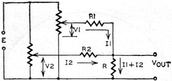
Fig. 3 - Mr. Math's easy-to-build circuit. Now let's take a closer look at the circuit (Fig. 3) of this calculator we're going to build. The letters which identify the potentiometers correspond to the front-panel markings on the controls and dials. Pot A (R5) furnishes a voltage output proportional to a dial-number setting as explained in conjunction with Fig. 1-b. Pot B (R6) furnishes a voltage output proportional to a dial-number setting multiplied by the control pot BE (R4) setting of 1/2, 1 or 2. This circuit is similar to that of Fig. 1-c. The outputs of pots A and B add in the summing network consisting of R7, R8 and R9. This is an application of the circuit of Fig. 2. The voltage representing this sum is introduced to one side of the meter. The sum of the output of pots C (R14) and CM (R13) connects to the other side of the null meter. This summation takes place in the summing network consisting of R10, R11 and R12. The output of pot C is proportional to the number set on the dial. The output of pot CM is proportional to 0, 1 or 2. The numbers stated are for the linear scales on the dials (see Fig. 4). The calculator equation for meter null with these scales is: (A) + (BM) (B) = (CM) + (C) where BM = 0, 1/2 or 2; CM = 0, 1 or 2 and A, Band C are continuously variable from 0 to 1.00 with dial scale divisions of .02. This equation provides for adding and subtracting. But Mr. Math computes to only two significant figures. Since addition and subtraction can be performed rapidly with paper and pencil, principal calculator applications are in multiplication and division. R1 - 220 ohms R2 - 32 ohms R3 - pot, 40 ohms, wirewound, screwdriver adjust (Mallory C40P or equivalent) R4, 5, 6, 13, 14 - pots, 100 ohms, wirewound (Clarostat 58C1-100 or equivalent) *R7, 8, 11, 12-2,700 ohms, matched to 1/2% *R9, 10-680 ohms, matched to 1/2% All resistors 1/2-watt 10% unless noted Use 1% resistors if you do not have access to a Wheatstone bridge M-50-0-50 μa (Triplett 327-T or equivalent) S1, 2 - spst, normally open, momentary contact type (Cutler-Hammer 8411-K4 or equivalent) Chassis, 2 x 13 x 7 inches Knobs Miscellaneous hardware
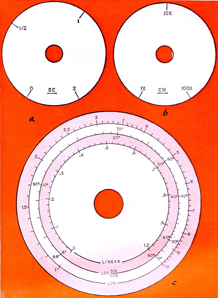
Fig. 4 - Calibrated dials for Mr. Math: a and b - The end marks (0, 2, 1X and 100X) are placed at the extremes of the mechanical rotation (300°). In use, these dial settings are not critical. The 1/2, 1 (on BE) and the 10X (on CM) settings must be accurate. Do not ink in the 1/2 mark on BE until calibration is completed. c - Linear and log scales are marked off on all three main dials.
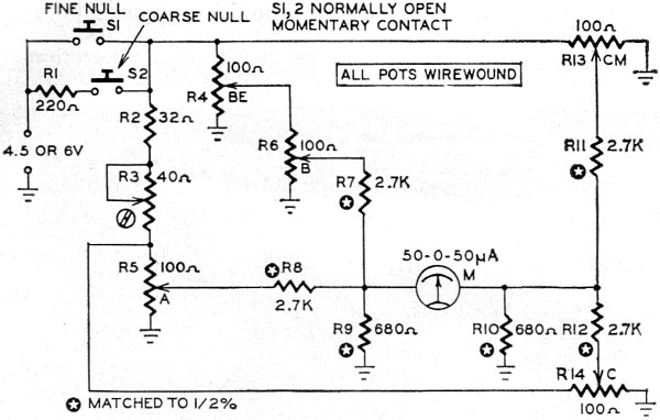
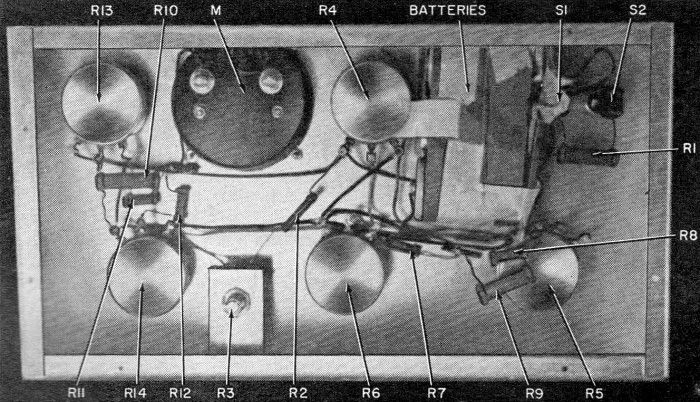
Inside view shows location of parts. I taped the batteries to the case, but a battery holder could be used for a more secure mounting. By assuming that the linear scales of pots A, Band C are the logarithms of numbers, new scales can be provided which are logarithmically related to the linear scale. Thus, with Mr. Math you can multiply, divide, square and take square roots. These are the most commonly required calculations in electronic work and they're the most time-consuming. The calculator equation for Mr. Math using the log scales (outer scale in Fig. 4) is: A X BBE = C X CM where BE = 1/2 (for taking the square root of B), = 1 (if B is not to be squared or its square root taken) or = 2 (if B is to be squared) CM = 1,10 or 100 (to set the decimal point for the number on pot C) A, Band C are continuously variable from 1 to 10. Trig scales and scales of numbers multiplied by commonly used constants (eg, 2π) may be laid out against the log scales to increase Mr. Math's memory. The three large dial scales have a 4-inch diameter. These are prepared by first laying out a linear scale with a radius of 1 1/4 inches. The calibrated portion of the scale covers 280° and principal divisions are spaced 28°apart. The full-scale value is 10 and the 10 principal divisions are numbered from 0.1 to 1.0. After these are laid out, a 1 3/4-inch radius circle is drawn for the logarithmic scale. The principal points for this scale were laid out using a log table or a slide rule. Remember that the inner linear scale corresponds to logarithms. There is enough space for an additional scale with a radius of 1 1/2 inches on each dial. My calculator has a log 2π scale in this space on the A pot dial, a log tangent-cotangent scale in this space on the B pot dial and a log sine-cosine scale in this space on the C pot. The explanation of these middle scales and their layout is difficult. Unless you've had a good bit of trigonometry, I suggest you wait to lay these out until you've become accustomed to Mr. Math's operation with the inner and outer scales. Mr. Math's scales are somewhat consistent with slide-rule scales. This allows you to use either without confusion if you know how to use a slide rule or learn how to use one in the future. The calculator draws current from the battery only when the Coarse Null or the Fine Null button is depressed. The Coarse Null switch is depressed first and an approximate null is established. Then the Fine Null switch is depressed and fine null is established. Calibrating Mr. Math A series of adjustments of the pointer knobs and one semi fixed pot is used to calibrate your calculator. The technique used is to set in several sample problems and adjust for the correct answer. You might call it an approximation method. Here's what to do: 1. Index knobs. Proper indexing is set when the hairline overrides the extreme clockwise and counterclockwise index marks by equal amounts. 2. Set controls so that (numbers given for A, B, and C are on linear scales) A = 0, B = 0.5, C = 1.0, BE = 2, CM = 1X Adjust the 40-ohm screw-adjust pot under the panel (R3) for null with the fine-null switch depressed. 3. Set controls so that A = 0, B = 0.5, C = 0, BE = 2, CM = 10X Check the null. If it is poor, adjust CM for null with the fine-null switch depressed. Loosen the knob setscrew on CM and move the knob until the hairline coincides with 10X again. Tighten the knob setscrew. Check to be sure that the null was not disturbed. 4. Set controls so that A = 0, B = 1.0, BE = 1, C = 1.0, CM = 1X Depress the Fine Null switch. If the null is not exact, turn BE for exact null, loosen the setscrew on BE and adjust the knob till the hairline coincides with 1. Tighten the knob setscrew. Check to be sure that the null was not disturbed. 5. Set controls so that A = 0, B = 1.0, BE = 1/2, C = 0.5, CM = 1X Depress the Fine Null switch. If null is not exact, adjust BE for exact null and place a new graduation line for 1/2 on BE. The dial indexing and calibration should be rechecked if error greater than 3% is noted on any calculation . To use Mr. Math The calculator is used a follows: 1. To add two numbers (3.5 + 4.5, for example) use linear scales. a. set A at 0.35. b. set B at 0.45. c. set BE at 1. d. set CM at 1X. e. adjust C for meter null, read answer on C. C nulls at 0.80. (The answer is 0.80 X 10. The multiple is used since the numbers were divided for entry.) Note: If the sum of the numbers is greater than 10, set CM to 10X. The answer is 10 plus the number at which C nulls. Thus to add 7.2 and 8.7: a. set A at 0.72. b. set B at 0.87. c. set BE at 1. d. set CM at 10X. e. set C for meter null, read answer on C. C nulls at 0.59. [The answer is 10 X (1 + 0.59) or 15.9.] 2. To subtract two numbers (8.3 - 4.1, for example) use linear scales. a. set B to 0.41 (number to be subtracted). b. set C to 0.83 (number to be decreased). c. set BE to 1. d. set CM to 1X. e. adjust A for null. A nulls at 0.42 (The answer is 10 X 0.42, or 4.2.) 3. To multiply two numbers (3.9 X 7.1) use log scales. a. set A at 3.9. b. set B at 7.1. c. set BE at 1. d. set CM at 1X. e. attempt to adjust C for null. If null is not possible, set CM to 10X and adjust C for null. C nulls at 2.77. (The answer is 10 X 2.77, or 27.7.) 4. To divide one number into another (26/3.1, for example) use log scales. a. set C to 2.6. b. set CM to 10X. c. set BE at 1. e. adjust A for null, and read answer on A. A nulls at 8.4. (This is the answer.) 5. To square a number (7.92, for example) use log scales. a. set B at 7.9. b. set BE at 2. c. set A at 1 on log scale. d. set CM at 1X and adjust C for null. e. If no null can he obtained, set CM to X10 and adjust C for null. f. C nulls at 6.22 with CM at 10X. (the answer is 6.22 X 10, or 62.) 6. To take the square root of a number (8) use log scales. a. set B at 8. b. If number has odd number of places, set A at 1. If number has an even number of decimal places, set A at 3.16. Set A at 1. c. set BE at 1/2. d. set CM at 1X. e. adjust C for null. C nulls at 2.8. (This is the answer.) Since the computer may have an error of 1 or 2%, answers should be read out to only two significant figures. Thus, 27.7 should be read as 28, 272 as 270. Since the A, Band C log scales are scaled from 1 to 10, multipliers of 10, 100, etc. are used to represent numbers greater than 10. Thus to multiply 71 X 832, the dial settings of A and B are the same as for 7.1 X 8.32. and the result from CM and C is multiplied by 10, 100 or 1,000 to get the final answer. The trigonometric scales (which I suggested you add later) are actually 10 times the respective functions which they represent. This requires the use of a scaling factor in the answer. Thu 5 tan 45° gives the result 50 on C and CM. This result must be divided by 10 to obtain the correct answer. To get most accurate results from your construction work: a. Match R7, R8, R11, and R12 within ±1/2% with a Wheatstone bridge. b. Match R9 and RIO within ±1/2%. c. Use the potentiometers specified; others may not possess the linearity required. d. Prepare dial scales accurately. Be sure knob pointers fit close to scale to prevent parallax errors. e. Calibrate carefully according to the procedure outlined, f. Set numbers into the calculator accurately when working problems. Happy calculating!
Posted April 30, 2020 |
|