Build a Mini−Tenna
|
|
Build a Mini−Tenna
Build a Mini−Tenna for FM Radio By James A. Gupton, Jr. Here's a construction project designed around one of the most controversial recent developments in electronics - the Subminiature Integrated Antenna, or SIA. You can build it in less than an hour, for only a few dollars. And you'll be learning something about the latest state-of-the-art development in antennas. Background of SIA In the spring of 1967 a new military communications development was revealed.* Researched and built by the US's Edwin M. Turner and Germany's Dr. Hans Meinke, the SIA was branded with an astounding claim - only 1/50 wavelength long, it can perform as well as a conventional quarter-wavelength model. Normally, a small antenna (with respect to wavelength) has little capture area, hence doesn't pick up much RF signal. Thus gain is low and the antenna is inefficient. At frequencies above about 30 MHz, moreover, the signal-to-noise ratio of a small antenna is poor. Generally, then, an antenna should be a quarter-wavelength or longer in size to provide a clean signal.
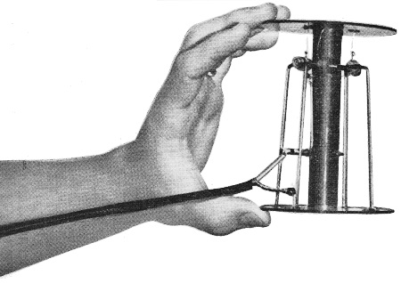
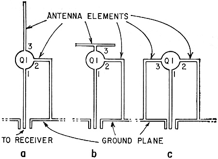
Fig. 1 - Secret of SIA is that transistor becomes integral part of antenna.
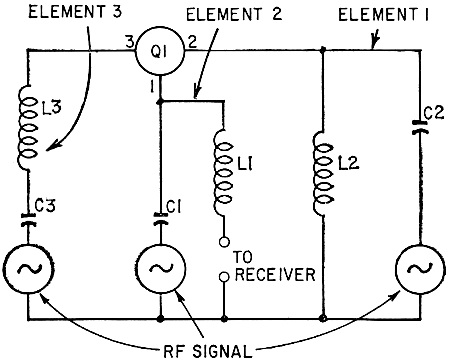
Fig. 2 - Equivalent circuit of SIA's shown in Figs. 1-a and 1-b, RF signal is picked up by all antenna elements. In the SIA, transistors are connected directly to antenna elements. Thus the transistor multiplies the RF current in the antenna element by a factor equal to the gain of the transistor. Another way of looking at the situation: In a passive (conventional) antenna, resonant frequency depends solely on element length (unless electrically altered by inserting capacitance or inductance). But the SIA's transistors lower the resonant frequency. They also make the frequency response quite broad, so a few inches of wire will have good response. Its developers claim that the SIA can operate over a wide frequency band-from a ratio of 2:1 to perhaps 50:1. Because the bipolar transistor used is a low-impedance device, an SIA usually needs no special matching circuit to drive coaxial cable directly. Some antenna engineers, however, question the value of SIA. The same results could be obtained, they say, by using an ordinary passive antenna with a booster. Transistor noise levels, they note, can also limit performance of the SIA. And no study has been made of cross-modulation in the new device. The controversy grew when some predicted a 2-inch-long SIA for home TV receivers would obsolete rabbit ears and rooftop antennas. But it mustn't be overlooked that the tiny antenna was developed for military use where large antennas simply can't be used and where some inefficiency must be tolerated. How It Works The simplest form of an SIA is merely a transistor connected to antenna elements in anyone of three basic forms (Fig. 1). The ground plane is connected to one side of the lead-in, and a transistor lead to the other side. In Fig. 2 you can see the equivalent circuit of antennas Band C of Fig. 1. Generator symbols represent the RF signal picked up by the three antenna elements. Distributed capacitance and inductance are shown, as well as the transistor and the lead-in terminals. Note that antenna elements 1 and 2 form loops, and respond to the magnetic RF field. All three elements respond to the electric field. There are also three ways to connect a transistor to the antenna elements (Fig. 3). The emitter-base lead-in connection (B) seems the most likely to match low-impedance coaxial cable and receiver inputs. A practical model of this antenna might look somewhat like Fig. 4. FM Mini−Tenna
Fig. 3 - Three transistor elements may be connected three ways in the SIA.
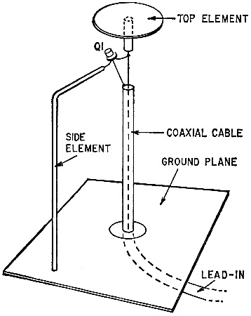
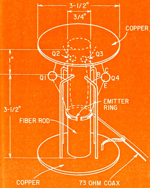
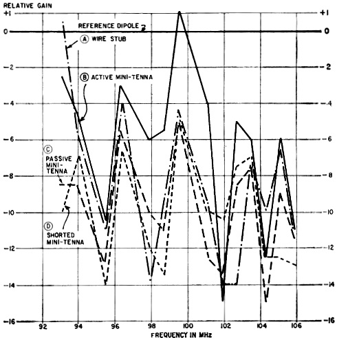
Fig. 4 - Developmental version of SIA shows practical method of connections. My choice for an experimental model of an SIA was what I call a Mini−Tenna, for it stands only 4 1/22 inches high and is 3 1/2 inches in diameter. You can see the simple construction in Fig. 5. A 3/4-inch-diameter fiber rod forms the main support (you can also use Lucite, wood or any nonconductor here). At each end of the rod is a 3-inch-diameter round piece of copper-clad print board (a piece of sheet metal will do) - one forms the top hat, the other the ground plane. The copper sides of the boards face inward. Four lengths of No. 10 copper wire form the side elements, and another section of wire the emitter ring. The electrical circuit, shown in Fig. 6, is just as simple. Not shown here are the distributed capacitances and inductances in the metallic elements. Battery bypass capacitor C1 is merely a gimmick with a value of a few picofarads. You can solder a short piece of hookup wire to each battery terminal, then twist the insulated ends together to form the gimmick. Mini-Tenna's dimensions are cut to about 1/35 wavelength (at 100 MHz). I tried a 1/50 wavelength model, but the present antenna performs better. Since the antenna isn't sharply resonant, but is broadband, exact dimensions don't seem too important. In fact, the larger the antenna, the more capture area, and the more signal. New experimental antenna blends solid-state elements with conventional skywire in new approach. Mini−Tenna Performance Two Radio-Electronics editors borrowed author Gupton's small antenna to evaluate its performance. Their reports follow. I compared the Mini−Tenna pickup capability with that of a dipole. The reference antenna was a 50-inch, 72-ohm open dipole, gamma-matched to 72-ohm coaxial cable. I oriented the dipole horizontally, north south, and placed it 7 feet above the floor of my ground-floor apartment in Manhattan, at a location where the field intensity of the stronger local FM stations is approximately 250 to 500 mV/m. The coax was fed through a 72-to300-ohm balun into my mono Eico HFT-90 FM tuner. In the tuner, the AGC network was disabled and all stages run at constant gain. The limiter grid voltage was monitored by a Heathkit IM-25 solid-state vom with 11 megohms input resistance. This monitored DC grid voltage was then essentially proportional to received signal intensity. First I made a control run, measuring limiter grid voltage for signals from 14 local FM stations. Later measurements were plotted against this reference run. Next I physically removed the dipole from its mounting at the end of the coax, and inserted a 4 1/2-inch stub of wire in the coax plug; I oriented the wire vertically. The stub represented the Mini−Tenna reduced to the bare minimum. By re-measuring the same 14 FM stations, and plotting the differences against the reference dipole readings, I got curve (A) (see graph). Then I mounted the Mini−Tenna in place of the wire stub - at the same point the dipole had been. With a 22-volt battery and a bypass capacitor in place, the "active" curve (B) was obtained. Next I removed the battery and placed a jumper across the break in the coax shield; this produced "passive" curve (C). Finally, all transistors were removed from their sockets and a short jumper was placed between the emitter ring (at the point where the coax ties to it) and the top hat. This gave curve (D), or "shorted."
Fig. 5 - SIA construction uses capacitance of top and bottom "hats" for wide frequency response.
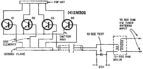
Fig. 6 - Diagram shows DC and mechanical circuit for the SIA, but not distributed capacitance and inductance. As the graph indicates, there seems little difference in the pickup of the wire stub, the shorted or passive Mini−Tenna. It appears that the mass of metal in the Mini−Tenna, as well as the unpowered transistors themselves, contribute little or nothing to signal pickup. The active Mini−Tenna, however, seems to produce some significant improvement over the other modes of operation. It hasn't the pickup of a dipole, but it did produce fully quieted signals on local stations. The Mini−Tenna seems essentially nondirectional, but this might or might not be an advantage in metropolitan receiving locations. I did not evaluate this antenna for stereo. - Thomas R. Haskett
Response curves of Mini−Tenna vs reference dipole. I found the Mini−Tenna to have no discernible effect (good or bad) on stereo FM reception at my apartment in Brooklyn. Presumably the broadband character of the antenna makes it frequency-flat and phase-flat over the necessary range of frequencies, so that stereo separation isn't affected. However, like all more-or-less omnidirectional antennas, this one may intercept delayed reflections of signals just as well as it intercepts the direct signal from the transmitter; hence it may give distorted reception or poor separation on some FM stereo stations. Signal strength was higher with the battery jumper open than with it closed (when the battery was not used). The gimmick had no noticeable effect. A 0.001 μF disc ceramic bypass capacitor connected in place of the jumper had the same (negative) effect as closing the jumper. (The reactance of 0.001 μF at 100 MHz is approximately 1.5 ohms.) This suggests that the gimmick has no significant bypassing effect. I estimate its reactance (100 MHz) at 1000-2000 ohms - vastly greater than the impedance of the battery or that of any other component in the system. In short, the Mini−Tenna seems to perform about as well as a small piece of wire. - Peter E. Sutheim R -E * See "Major Antenna Breakthrough?" in News Briefs, Radio-Electronics, July 1967.
Posted April 28, 2023 |
|

 Here is an excellent
example of how scientific evaluations performed by two independent subject
experts can result in significantly different conclusions. James Gupton, Jr.,
reports on what previously had been considered secret military technology - an
active, electrically small receiving antenna. This particular example, dubbed
the Mini−Tenna, is designed for use on the FM radio band. After building and
testing his antenna, Mr. Gupton offered it to two Radio-Electronics
magazine editors for investigation. Each used a carefully considered method in
what are generally similar environments - urban dwelling with strong signals and
opportunity for multi-path, connected to a commercial FM radio receiver. The
divergent results were not commented upon by the author. As a side note, I still
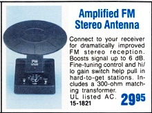
have a 1980s vintage active FM radio antenna from Radio Shack (Archer 15−1821).
It does as good of a job at pulling in stations as the half-wave dipole antenna
mounted in the attic. The dipole needs to be positioned fairly precisely to pick
up one station I listen to often, whereas the electronic antenna can be set just
about anywhere.
Here is an excellent
example of how scientific evaluations performed by two independent subject
experts can result in significantly different conclusions. James Gupton, Jr.,
reports on what previously had been considered secret military technology - an
active, electrically small receiving antenna. This particular example, dubbed
the Mini−Tenna, is designed for use on the FM radio band. After building and
testing his antenna, Mr. Gupton offered it to two Radio-Electronics
magazine editors for investigation. Each used a carefully considered method in
what are generally similar environments - urban dwelling with strong signals and
opportunity for multi-path, connected to a commercial FM radio receiver. The
divergent results were not commented upon by the author. As a side note, I still
have a 1980s vintage active FM radio antenna from Radio Shack (Archer 15−1821).
It does as good of a job at pulling in stations as the half-wave dipole antenna
mounted in the attic. The dipole needs to be positioned fairly precisely to pick
up one station I listen to often, whereas the electronic antenna can be set just
about anywhere.