Know Your L- and T-Pads
|
|
The terms "L−Pad" and "T−Pad" refer to the schematic circuit layout of the variable resistors (potentiometers) used to form variable attenuators. An L−Pad uses a series and parallel (shunt) resistor combination inserted between the source and load. A T−Pad uses a parallel (shunt) resistor between two series resistors. Potentiometer values are chosen to maintain a fairly constant input and output impedance throughout the attenuation adjustment range. Resistance charts are provided rather than design equations, but they are the same as those used for RF type attenuators of the same topography ("L," "T," "Pi"). Using the example for the T−Pad in this 1967 Radio−Electronics article and the calculator I have on the webpage, plug 16 Ω into the Input Resistance and Output Resistance fields and 4.375 dB into the Attenuation field, and it will yield the resistor values shown below. The article's author stipulates 9.65 dB, but that is voltage decibels. The RF calculator is for power decibels, so half the voltage attenuation decibel value is entered. Know Your L- and T-Pads - How to set up stereo and hi-fi systems with speakers in several rooms.
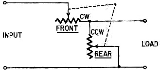
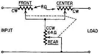
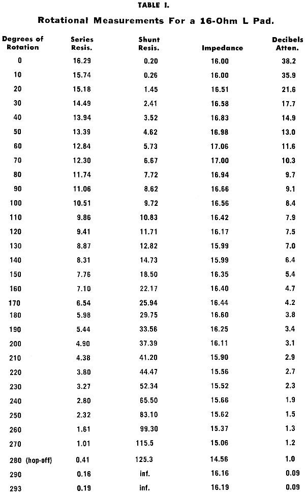
Know Your L- and T-Pads (this is an L-Pad) By James A. Fred Frequently, it is necessary to vary the volume of a loudspeaker independently of the amplifier, as in the case of a remote speaker in a bedroom. To achieve attenuation and to avoid the introduction of distortion, a "pad" can be used. A pad is an attenuator that does not change the circuit impedance as attenuation is varied. The L-Pad The L-pad is less expensive to build than the T-pad, since only two resistance sections are ganged together. The resistance element in the front section is called the series leg; the back element is called the shunt leg. The L-pad (Fig. 1), consisting of two sections, maintains the circuit impedance independent of attenuation at only one pair of terminals. To analyze the operation of an L-pad, refer to Table I, "Rotational Measurements for a 16-Ohm L-Pad." As an example, let us use a 16-ohm speaker connected to a 16-ohm L-pad and an amplifier. (The data in this table are actual measurements made on production L-pads.) Notice that the resistance of the series leg is the same as the characteristic impedance of the L-pad, while the resistance of the shunt is eight times as much. At the counterclockwise end, or 0° of rotation, series resistance is 16.29 ohms, shunt resistance 0.2 ohm, impedance 16 ohms, and attenuation 38.2 dB. At 50% or 150° of rotation, series resistance is 7.76 ohms, shunt resistance 18.5 ohms, impedance 16.35 ohms, and attenuation 5.4 dB. At 100% or 293° of rotation, series resistance is 0.19 ohm, shunt resistance is infinite, impedance is 16.19 ohms, and attenuation is practically zero. As the L-pad is rotated from one end to the other, the impedance stays essentially the same.
Fig. 1 - Diagram of a variable L-pad.
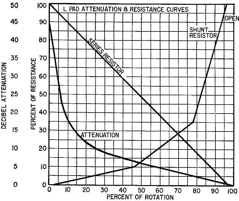
Fig. 2 - How attenuation of L-pad changes as shaft is rotated.
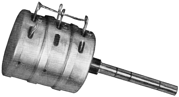
Fig. 3 - A typical 8-ohm variable T-pad.
Fig. 4 - Typical attenuation curves for a variable T-pad.
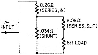
Fig. 5 - Equivalent circuit of a T-pad and its load set up for the maximum loss.
Fig. 6 - A variable bridge-T attenuator has only two elements which change value. ("Front" and "rear" labels are reversed.)
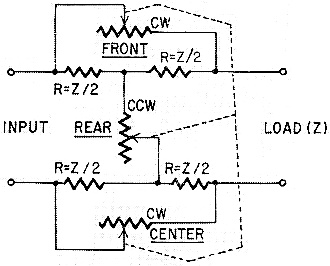
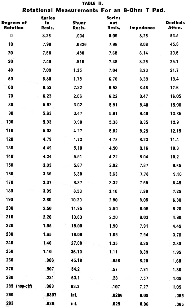
Fig. 7 - Variable bridge-H attenuator has three variable and four fixed resistors. The graph of Fig. 2, "L-Pad Attenuation and Resistance Curves," can be used to approximate the necessary resistance values for the resistance legs. Notice that the series leg is linear, while the shunt resistor is a tapered winding in three linear sections. This tapered winding gives the L-pad a more nearly linear attenuation. Total resistance of the shunt leg will be eight times that of the series leg. The series resistance will be the same as the rated impedance of the L-pad. Total attenuation is 45 dB. Since the threshold of audibility usually is assumed to be -60 dB, you will still be able to hear a signal even with the L-pad turned to the counterclockwise end of rotation. If it becomes necessary to cut the sound out completely, a switch must be used to open up the line. If so, it would be best to have the switch substitute a fixed resistor of the same value as the L-pad, to maintain proper loading in the circuit. L-pads can be used as described to control the volume of loudspeakers, but T-pads are generally preferred for this purpose, as explained in the following section. The T-Pad Where it is important that an attenuator and the amount of attenuation have no effect on circuit impedance, a T-pad is used. The T-pad (see photo and Fig. 3) consists of three control sections ganged together and operated by a single shaft. The front and middle elements have resistance values equal to the impedances they are to be matched to, and are referred to as the legs. The resistance of the rear element, or shunt leg, is usually eight times the value of either of the series legs. Table II, "Rotational Measurements for an 8-Ohm T-Pad," shows how the T pad operates. When the control is at the ccw end of rotation, the input series resistance is 8.26 ohms, output series resistance 8.09 ohms, impedance 8.26 ohms, and attenuation 53.5 dB. At 50% or 150° rotation, the input series resistance is 3.93 ohms, output series resistance 3.92 ohms, impedance 7.87 ohms, and attenuation 9.65 dB. At full clockwise rotation, the input series resistance is 0.036 ohm, output series resistance 0.029 ohm, impedance 8.06 ohms, and attenuation practically zero. From one end of rotation to the other, the T-impedance stayed at essentially 8 ohms. The graph of Fig. 4, "T-Pad Attenuation and Resistance Curves," can be used to approximate the resistance necessary for the resistance legs. For example, let us say that we need a 16-ohm T-pad. From the curves, we find that the series leg will be a 16-ohm linear-wound element, and that two will be needed. The shunt element will be eight times this value, or 128 ohms, made in three linear sections. The first section of the shunt element should be 10% of the overall resistance, or about 13 ohms in the first 55% of rotation. The second section should be 15% of the overall resistance, or 20 ohms in the next 21% of rotation. The third section of the shunt winding should be 75% of the overall resistance. or 95 ohms in the next 21% of rotation. The shunt coil is open for the last 3% of its rotation.
Table I.
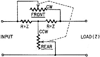
Table II. Those who are content to accept the preceding explanation on faith alone can stop here, and will probably be satisfied to buy and use L- and T-pads as always in the past. For those who are mathematically minded, we will proceed a little deeper into the subject. The attenuation of a resistance pad is expressed as a number of decibels (dB), where the dB expresses the ratio between two different amounts of power at two points-input and output, in this case. Strictly speaking, dB's can be used to express voltage or current ratios only when the two points in question have the same impedance value. However, when matching stereo controls in actual practice, input and output impedances are ignored. It is mainly in speaker matching, in the telephone industry, and in the broadcast industry that impedances are so critically matched. Let us go back to the impedance of the T-pad and draw an equivalent-circuit diagram (Fig. 5), but with a load. As you can see, the first series leg (8.26 ohms) is in series with the shunt leg (0.034 ohms), which is in parallel with the second series coil (8.09 ohms), which is in series with the 8-ohm load impedance. Working it out in simple arithmetic, we have 16.09 ohms in parallel with 0.034 ohm, which gives us 0.03 ohm. The 8.26 ohms and 0.03 ohm added together give us approximately 8 ohms, the nominal impedance of this T-pad. An equivalent-circuit diagram of the L-pad can be drawn and analyzed the same way. This article is limited to L- and T-pads, because these are the ones most readily available to technicians and experimenters. There are other types. Instead of T-pads, some companies supply variable bridged-T pads; these require only two variable sections plus two fixed resistors. This is less expensive and, in many cases, a bridged-T pad (Fig. 6) will work adequately in place of a straight 3-section T-pad. Another type usually available on request is the bridged-H pad (Fig. 7). This pad consists of a conventional T-pad with four fixed resistors connected as shown. The resistors help to give a more linear attenuation curve.
Posted September 19, 2023 |
|