Know Your Levels |
|
The old adage about a picture being worth a thousand words is still true today, even in the Information Age in which we live. A lot of people, especially those new to the field of electronics, struggle with the concept of decibels as applied to power and voltage (and to a lesser degree current). A plethora of computer, browser, and phone app programs are available to make individual, specific conversions, but what has been learned about the fundamental relationship? A nomograph is still one of the best tools both for teaching and performing conversions. This article that discusses properly matching impedances of amplification stages includes a nice nomograph. Know Your Levels
Both low - and high-level amplification have built-in complications. Discover what they are and how to beat them. Some things about designing or using amplifiers you can find in any textbook. But for some unexplainable reason other items of information that ought to be easy to find seem to get left out. For example, operating levels at various points in an audio system. The amplifier user needs to know this so he can put the right items of equipment together and get the best performance out of the whole system. The amplifier designer needs this knowledge to select the right components for his amplifier. A closely related piece of information - that of impedance matching - gets discussed in every second article on amplifiers. So it is common knowledge that a 50-ohm microphone must be connected to a 50-ohm amplifier input. A number of articles have shown how to make resistance pads to match one impedance to another.
Fig. 1 - Cascode input circuit for pre-amplifier input stages where noise must be minimized. Resistors and capacitors should be high-stability low-noise components. I was called in recently on a case which aptly illustrates the lack of this knowledge. My job was to make a microphone-amplifier-loudspeaker combination work. The man who called me had paid careful attention to matching. The microphone was 50-ohms and the amplifier had a 600-ohm input, so he used a line transformer from microphone to amplifier. However, he was unable to get any output from the system.I was called in recently on a case which aptly illustrates the lack of this knowledge. My job was to make a microphone-amplifier-loudspeaker combination work. The man who called me had paid careful attention to matching. The microphone was 50-ohms and the amplifier had a 600-ohm input, so he used a line transformer from microphone to amplifier. However, he was unable to get any output from the system. Examination showed that the amplifier was designed to operate from an input level of 0.5 to 1 volt at 600 ohms. The microphone was one of the higher-sensitivity dynamic types which gives about 3-mv output across 50 ohms for normal speech. The matching transformer from 50 to 600 ohms stepped this voltage up about 3.5 times, delivering a little more than 10 mv to the amplifier. But 10 mv is not enough for an amplifier that needs an input of 0.5 volt (500 millivolts). "You need more amplification," I told my caller. "That's easy," he replied, "I have another of these amplifiers here on the shelf, and you know how to make a matching pad so I can work the 16-ohm output of one into the 600-ohm input of the other." I explained that what he needed was not another power amplifier but a preamplifier for working at low level. This he did not seem to understand. He thought amplification was amplification, and between the two amplifiers there should be enough of it. So I explained briefly why this arrangement would not work. But how many of us have had to find this out the hard way - by trying it - simply because there was no one on hand to tell us what would happen? Fortunately this job did not prove difficult, because he did have a comparatively high-sensitivity microphone and it wasn't too hard to find a preamp that would work successfully with this power amplifier. If he had been trying to use a mike with a much lower output level, there would have been bigger problems in finding a satisfactory preamplifier. So let's start at the input end and see what it takes to make a good amplifier that will handle signals at all levels. Low-level components When we set out to build an amplifier for amplification at low levels, from insensitive microphones and pick-ups, particularly the ribbon type, we have to be very careful when selecting components. The first tube gets a maximum signal of only a few millivolts at its grid. It is expected to make these signals audible at the output. This is getting down to the level of tube hiss and the hum generated in a good many tubes.
Electronics voltage and power level nomograph. The input circuit must be carefully shielded to avoid hum pickup. This part of the story, though, has been well discussed elsewhere from time to time. Tube hiss is due to plate current, which consists of electrons flowing from cathode to plate. Each electron transit is a separate event, so the plate current is made up of a random sequence of separate charges passing from cathode to plate. The average rate of transit determines the measured current. When amplifying low-level signals, changes in plate current due to the applied audio grid voltage are not much more than the fluctuation in rate of arrival of electrons at the plate due to the random nature of their departure from the cathode. Therefore, tube hiss is apt to be almost as loud as the audio signal we want to use. Ways have to be found to minimize tube hiss. The noise a tube generates due to these effects is obviously proportional to the total current flowing - the proportion of fluctuation in electrons arriving at the plate is proportional to the average total number arriving. The noise voltage they develop at the plate is also proportional to the fluctuation in the velocity at which they arrive. The fluctuation in velocity is proportional to the actual velocity. Therefore, halving the plate current will approximately halve the noise output of a tube and halving the plate voltage will also approximately halve the output. But halving the plate current or plate voltage does not necessarily halve the tube's gain. Over a wide range of variation in plate current and voltage, a tube's amplification does not vary by too much. Operating the tube with low plate voltage and current gives almost the same amplification as a higher plate voltage and current, but considerably reduces noise introduced by the tube. From the standpoint of noise, two things are required of an input stage: (a) it must have minimum noise itself; (b) it should have as much gain as possible, to lift the signal as far as possible above noise. Pentodes have good gain, but generate more noise than triodes. About the best compromise seems to be the use of a twin triode in the cascode circuit shown in Fig. 1. Another factor in operating tubes at low levels is their microphonic characteristics. A tube's plate current is determined by the electric field produced by the grid and plate at the cathode. Fluctuations in this field vary the plate current and this constitutes signal. If one of the electrodes, particularly the grid, is subject to any vibration, the field controlling the plate current is altered. As the variations we are concerned with are very small, it takes very little vibration to produce an audible output. This characteristic is known as microphonics. To prevent microphonics, special attention has to be paid to providing a rigid tube construction so the electrodes are not free to vibrate. Another way in which a tube can inject a spurious signal is by hum, especially if AC is supplied to its heater. Tubes designed for use at low levels have the heater specially constructed to radiate a minimum AC field. In short, a tube specially designed for operation in audio amplifiers at low levels has to have the following special characteristics: It should be a hi-mu tube which can be used with low plate voltage and current. Its construction should prevent microphonic vibration. The heater must be made so it doe not inject hum into these low-level circuits. One tube to which careful attention has been paid is the double-triode 12AY7. Usually, feedback is not applied over the first stage of an amplifier designed for low level inputs. This is because a feedback loop over a low-level input reduces the input voltage seen by the tube to a fraction of the input voltage provided by the microphone or pickup. This aggravates the noise problems we have been discussing rather than helping reduce them. Distortion problems However, in these days of low distortion, when some designers are working to get figures in the region of 0.1%, feedback is used to reduce the distortion factor of all the other stages to a minimum, so the input stage is sometimes the limiting factor in distortion. When this is first discovered, it comes somewhat as a surprise. The classic treatment of distortion tells us it is due to curvature of tube characteristics and, if we use the tubes well inside of their maximum rating, the distortion will be low. Surely, by using only a few millivolts of the tube's characteristic, distortion should be negligible. This you would expect. But it does not work this way in practice. You would expect a similar thing of high-quality transformers because their distortion is also due to nonlinearity. However, distortion measurements on the magnetizing current of high-quality transformer cores, suitable for input transformer use, show that reduction in level reaches an ultimate minimum in distortion - about 1% of the magnetizing current. Of course, the distortion is likely to show up only at low frequencies because the magnetizing current itself is a small fraction of the currents that the transformer handles as signal currents at frequencies above the low frequency cutoff. This means that such a transformer at low levels produces a distortion of maybe 0.5% in the region of 50 cycles, dropping to about 1/20th of this, or .025%, at 1,000 cycles. This residual value of distortion is due to a hysteresis effect in the magnetic core material. It appears, although little work has been published on this, that tubes exhibit a small "hysteresis" effect , which is normally so miniscule as no to be worth considering. But, in comparison with the minute fluctuation of current we have to handle in low-level input stages, this hysteresis effect in the tube current characteristic is enough to represent harmonic distortion of about 0.1 or 0.2%, according to tube type. This kind of distortion does not disappear - like the transformer magnetizing-current distortion - at higher frequencies, because the tube current fluctuations are the same whatever frequency the tube is amplifying. So, in selecting a tube for low-level amplification, a number of factors have to be considered. Fortunately, tube manufacturers as well as amplifier designers are working on this, so we are able to call on their assistance to provide the best tubes for the purpose. What the amplifier user has to realize, however, is that you cannot just plug in, say, a 12AX7 as a replacement for a 12AY7 because it happens to give a similar gain in the same electrical circuit. It may even give a little more amplification, but it will probably introduce other troubles which have been taken care of in the design of the 12AY7.
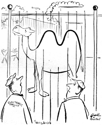
"That reminds me, I've got an FM alignment on the bench." Other components that need special attention in low-level input circuits are the resistors and capacitors. The capacitors must be low-leakage types. Their insulation resistance must be better than that required for normal amplifier applications, because any leakage through this insulation will cause increased noise. Resistors should be made of a highly stable material that will not give appreciably more than the basic minimum of noise due to thermal agitation, which is a characteristic of all resistors. The big problem in input transformers for low-level stages is shielding against hum pickup. Where the input level is very low, a triple-shielded transformer, giving a reduction in hum pickup of as much as 90 db, may be necessary. Now we can see why a power amplifier would not do as a substitute for a preamp to provide the initial stages of amplification. A power amplifier's input transformer is intended to handle a normal signal of 0.5 to 1 volt. In trying to work at a level of 10 mv, it will probably pick up excessive hum because there is no necessity for superfine shielding in this application. Further, the input tube of a power amplifier, while quite satisfactory for its purpose, would probably prove to be quite noisy and microphonic as well as introducing its own quota of hum when used for amplifying at low levels. High-level components From low-level operation we will turn to high-level operation because that is where the next group of problems arises. There seem to be no particularly tough problems in providing amplification at intermediate levels because then we are well away from the extremes which cause problems either low- or high-level operation. As you know, the big problem in high-level amplification is distortion. Here the curvature of the tube is the controlling factor. The problem of output stage design has been discussed many times, but there are other relatively high-level circuits where you must be careful in selecting tubes to give the best performance. For example, pursuing the comparison made between the 12AX7 and 12AY7 for low-level work, when we compare the data, we find that the 12AY7 gives a larger harmonic distortion than the 12AX7 for the same output level if the signal voltage on the grid is more than about 0.1 volt. Similar comparisons can be made between other tubes such as the 12AU7 and its nearest counterpart in the octal range, the 6SN7-GT. The 6SN7 will give both a little more output and a little less distortion than the 12AU7, operating as a single-ended tube. But at levels less than one-third of the maximum handling capacity, the 6SN7 gives considerable less distortion than the 12AU7. However, there is a consoling factor for the latter tube in that most of its distortion is second harmonic, and the pairs in the same envelope are usually pretty well matched.
Nomographs / Nomograms Available on RF Cafe: - Parallel Series Resistance Calculator - Transformer Turns Ratio Nomogram - Symmetrical T and H Attenuator Nomograph - Voltage and Power Level Nomograph - Nomogram Construction for Charts with Complicating Factors or Constants - Voltage, Current, Resistance, and Power Nomograph - Resistance and Capacitance Nomograph - Voltage, Power, and Decibel Nomograph - Resistance and Reactance Nomograph - Frequency / Reactance Nomograph
Posted August 21, 2020 |
|