Interference - Causes, Remedies and Location
|
|
Interference takes on many forms and can be caused by nearly an infinite number of sources. In 1960 when this article appeared in Radio-Electronics magazine, most manmade interference (QRM) originated in electrical machinery, faulty contacts in switches and lighting, improperly shielded and/or filtered RF generators, and arcing transmission lines. Natural interference (QRN) has not fundamentally changed since the same process continue to occur - lightning, meteoric ionization of the atmosphere, solar particles, etc. It was nearly all caused by analog processes. Nowadays, ambient noise both conducted and induced is as likely - or even more likely - to come from digital circuits. The base level (noise floor) of electromagnetic (EM) signals in a typical urban or suburban environment is significantly higher than it would have been in 1960. Fortunately, the same group of engineers and scientists that generated the condition have also figured out ways to mitigate the issues - for the most part. Some forms of increased EM interference will never be able to be compensated, like light pollution that degrades the quality of astronomical observation. It extends outside the visible spectrum into infrared and ultraviolet. In fact the situation is so bad that projects are underway to build giant telescopes on the far side of the moon in order to shield detectors from Earth-sourced interference. Interference - Causes, Remedies and Location
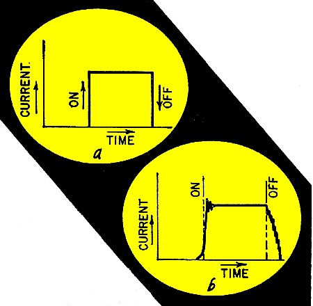
Fig. 1 - Waveform of a: ideal and b: practical switch operation. Problems with TV sets and radios can generally be solved by finding out what causes the interference as the first step in eliminating it By Forrest H. Frantz, Sr. Electrical interference is annoying to the broadcast listener, exasperating for the shortwave listener and frustrating to hams. Natural electrical interference cannot be controlled; man-made interference can. The effects can often be eliminated at the receiver, but in some cases interference must be eliminated at the source. To cope effectively with electrical interference, it is important to understand how it's generated and transmitted. When the type is recognized, the source can be found and eliminated. The causes of man-made interference fall into four general categories: 1. Switching 2. Discharges 3. Radio-frequency leakage 4. Harmonic generation Switching noise occurs at electrical switches and commutators. Typical offenders are: light switches; thermostats on electric irons, heating pads and home heating systems; switches and flashers on advertising signs; commutators on electric motors, industrial equipment and home appliances, and poor electrical connections.
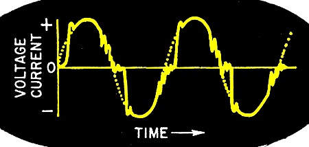
Fig. 2 - Current in a glow discharge tube goes through several high-frequency oscillations each cycle.
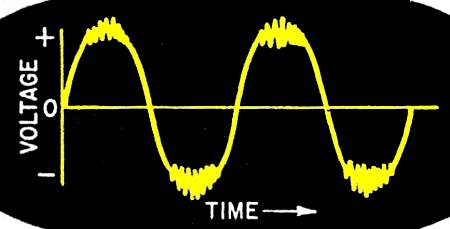
Fig. 3 - High-voltage corona discharge nor-madly occurs during voltage peaks.
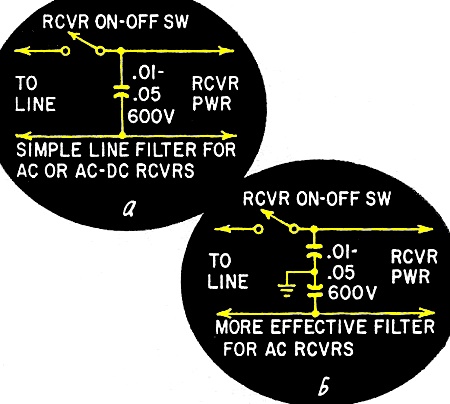
Fig. 4 - Line filters for a: ac and ac-dc and b: ac only receivers.
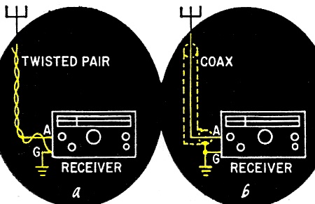
Fig. 5 - Shielded and twisted-pair ins reduce noise.
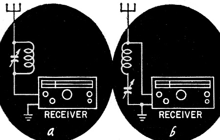
Fig. 6 - a: parallel-resonant wavetrap in series with antenna, b: series-resonant trap across antenna-ground terminals.
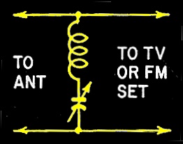
Fig. 7 - Series-resonant wave trap may be connected directly across transmission line.
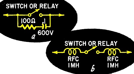
Fig. 8 a: R-C combination suppresses arcing, b: rf chokes can be used on device where timing is important.
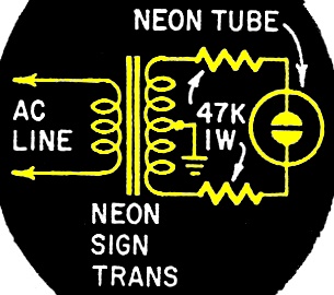
Fig. 9 - Resistors damp oscillation in neon tubes. This interference is caused by arcing when an electrical circuit is opened or closed. Fig. 1-a shows the idealized waveform for switch operation, with its characteristic steep rise and fall. Fig. 1-b shows a practical waveform. The fall time is increased and current decay is irregular. The arc radiates a complex signal which contains many frequencies. An intermittent break in a poor electrical connection can be extremely harassing because arcs are continuously struck and extinguished in a haphazard way. Arcing is a type of electrical discharge that occurs at relatively high currents (generally 100 ma or more). Glow discharges such as those associated with neon and fluorescent lamps occur at intermediate currents (generally a few microamperes to several milliamperes). Glow discharge tubes are ordinarily ac-operated. The ac voltage acts as a switch for the discharge. The resulting interference looks like the waveforms of Fig. 2. The voltage increases from zero to the glow striking voltage. The tube fires and the current drops in an oscillatory manner till the voltage reaches the extinguishing value. Again a series of harmonic-rich oscillations occur as the current drops to zero. The process is repeated during the negative half-cycle. A total of four oscillatory discharges occurs during each voltage cycle, or 240 times a second with a 60-cycle line voltage! Corona discharges usually occur at extremely high voltages and are characterized by extremely low currents. Interference picked up on automobile radios while passing near high-voltage lines is due to corona discharge. This type of discharge occurs during the voltage peaks of the ac cycle. Fig. 3 shows the waveform. This interference may contain frequencies from the audio range up to several hundred megacycles. Radio-frequency (rf) leakage interference is generally caused by inadequate shielding of rf generators such as induction heaters, diathermy machines and high-voltage power supplies which employ rf oscillators. Occasionally, it's an interfering radio station. Interference of this type differs from the others-it is tunable. Harmonic interference is caused by generators of nonsinusoidal waveforms. Sawtooth and square waves contain many harmonics of the fundamental frequency. Thus, a 10-kc sawtooth signal might contain troublesome harmonics at frequencies as high as a megacycle. Remedies at the Receiver A receiver picks up signals with power levels of considerably less than a billionth of a watt. Although interference may reach a receiver by conduction through the power lines, most interference is picked up by the receiver antenna. Interference conducted to the receiver through the power lines may be radiated within the set and picked up by the receiver input circuit. Conduction of interference to the set via the power lines may generally be eliminated by connecting a capacitor of 0.01 to 0.05 μf across the ac lines for ac-dc receivers (Fig. 4-a). The arrangement in Fig. 4-b, with a capacitor from each side of the line to ground, may be employed for ac receivers. A 0.05-μf capacitor has a reactance of 3.18 ohms at 1 megacycle and 0.318 ohm at 10 mc. This is a near short circuit to rf signals. Interference introduced via the antenna is another matter. If the receiver uses a loop antenna, it may be possible to take advantage of the directional characteristics of the set. The other avenue open is to locate the noise and eliminate or suppress it at the source. The external antenna in this age of high-sensitivity receivers is frequently a piece of wire strung inconspicuously around the room. If the wire is close to a household power line or within several feet of a fluorescent lamp (and it often is), interference may be reduced by relocating the antenna wire or resorting to an outside antenna with a shielded or twisted-pair lead-in. The shield or unused wire in the case of a twisted pair should be connected to the receiver ground (Fig. 5). An outside antenna can become a source of noise in itself if the lead-in is not soldered to the antenna proper or if the lead-in is permitted to touch rain gutters or other metal objects. Tunable rf signals may be reduced with a wavetrap, Two types of wave-traps and their, connection modes are shown in Fig. 6. The inductance-capacitance combination is· the same as you'd use in a receiver to tune to the interfering station. Set the wavetrap capacitor for minimum signal pickup. The trap of Fig. 6-a inserts a large impedance between antenna and receiver at the interference frequency. The trap of Fig. 6-b places a low impedance across the antenna and ground terminals at the interference frequency. In a television receiver, interference signals below 50 mc may feed through the front end of the receiver and be amplified by the broad band if stages. High-pass filters which attenuate signals up to about 50 mc are available commercially. This type of filter is connected between the lead-in and the TV set's antenna terminals. The filter must be chosen to match the impedance of the transmission line-300 ohms for ribbon, 72 ohms for coax. If TV interference is tunable, a wavetrap may be employed. A single series-resonant trap connected across the transmission line terminals as shown in Fig. 7 is preferable. (This arrangement will also work on FM receivers.) Symptoms of interference that a filter or a trap might cure are noise streaks, sound bars and herringbone patterns on the picture. TV picture pulling and FM receiver cross-talk between adjacent stations can often be eliminated with a wavetrap tuned to suppress the stronger station. Locating the Noise If the suggested remedies applied at the receiver do not eliminate interference, you might as well get out your deerstalker and turn into a noise sleuth. If the noise is the result of non-sinusoidal signal generation, the source is usually a piece of electronic equipment. Television receivers are primary suspects. Find out if your own TV set is causing your interference by observing if the noise exists with the set on and disappears with it off. Discharge interference will be apparent at relatively high frequencies. Sources of thermostat arc noises and appliance interference created in your home are usually obvious, since you know when these devices are being operated. Assuming nothing this obvious, turn on a battery-operated portable radio and tune it off station. Pull the main fuse or switch on your house wiring panel. If the interference disappears or drops significantly, the noise source is probably connected to. the electrical circuit in your home. Now you can turn the main switch on and turn the other circuits off one at a time till the interference stops. From this point on, it's a matter of locating the offending appliance, lamp or defective wiring. A battery portable radio may be useful in locating the source of the noise by actually homing in on it. For this type of work, a battery receiver with a highly directional antenna and a signal-level meter such as the Heathkit DF-1 radio direction finder is invaluable. If the noise is not being generated on your premises, scout the neighborhood with your battery-operated portable. Remedies at the Source Remedies at the source depend, of course, on the type of interference. Noise due to. motor commutator arcing may usually be suppressed with a 1-μf 600-volt capacitor connected across the line terminals at the motor. A 0.1-μf 600-volt capacitor is more practical for portable tool and vacuum cleaner motors. The motor frame should be grounded as a safety as well as a noise precaution, A 0.02-μf capacitor connected from each side of the line to the grounded frame may reduce the interference further. In extreme cases, a commercial filter (a capacitor-inductor combination) may have to be used. Contact arcing on switches, relays and thermostats where currents of less than 3 amperes are involved may be reduced with a 0.1-μf capacitor connected across the contacts, To limit charge and discharge currents, a 100-ohm 1.2-watt resistor should be connected in series with the capacitor (Fig. 8-a). The voltage rating of the capacitor depends on the circuit inductance. If the contacts control a device for which timing is important, the R-C combination of Fig. 8-3, cannot be used. Instead, two 1-millihenry rf chokes of adequate current rating for the load may be connected as shown in Fig. 8-b. To suppress fluorescent fixture interference, connect a 0.05μf capacitor across the line and connect a 0.02-μf capacitor from each side of the line to the metal frame of the fixture. The filter should be mounted inside the grounded fixture frame. Interference from neon signs may be minimized by removing protruding points in the wiring which might allow auxiliary discharges and by cleaning switch contacts periodically. High-frequency oscillations may be damped by placing a 47,000-ohm resistor in series with each of the transformer secondary leads to the tubing (Fig. 9). Interference from automobile ignition systems to home receivers is rarely ever bothersome. But the ignition system will introduce noise to the automobile radio if it isn't suppressed. Ordinarily a resistive suppressor in the ignition coil lead to the distributor, and a 0.5- or 1-μf capacitor from the ammeter to ground will suppress ignition noise. This, of course, assumes a properly shielded antenna lead with a good shield connection to the auto frame. A 0.5- or 1-μf capacitor should be connected across the generator to suppress generator noise. In severe cases, particularly in older cars, additional measures may be required.
Posted July 19, 2023 |
|