Flyback and Yoke Tester |
|
Hmmm..., I think this article ended up being scanned because an electronics-themed comic appeared on the same page. Oh well, the information about building a simple, one-tube television flyback and yoke tester is still useful to somebody out there, so here it is.
Flyback and Yoke Tester
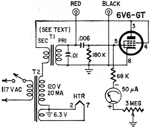
At one time or another every service technician has wanted to know if the flyback or yoke was actually bad before removing the old unit. I have repaired many sets for other shops and dealers whose verdict was "a bad transformer" which turned out to be damper circuit troubles or "a bad yoke" which turned out to be a shorted capacitor in the yoke. To solve the problem I designed a flyback and yoke tester. The unit is a blocking oscillator keyed by raw AC on the 6V6's plate and screen. The oscillator is keyed 60 times a second and operates at a low audio rate. A 6.3-volt heater transformer (T1) is used here, the heater winding being the plate winding. The power transformer was salvaged from an old uhf converter and has a 6.3-volt heater winding as well as a high-voltage winding rated at 120 volts at 20 ma. The meter I used comes from an old VTVM. No special layout is followed; that is left to you. To check a flyback, disconnect all yoke, width and AFC coil leads, leaving nothing but the high-voltage rectifier's filament. (To clear up a point, all leads won't have to be removed, just open leads so that the transformer isn't loaded by any windings. In a majority of recent sets without any width coils, just open one yoke lead.) When testing yokes, one end of any internal resistors or capacitors must be disconnected. The meter scale is colored red to 45 on its 100-volt scale (or 45% of scale) and green from 55-100 (full scale). At 67 (on the 100-volt scale, or 67% of scale) a calibrating mark was made. Most good transformers read higher than this calibrating mark. The black lead from the tester is connected to the flyback lead going to the plate of the high-voltage rectifier and the red lead from the tester goes to the horizontal plate lead. After warm-up, calibrate the unit and test the transformer. As stated, most flybacks read higher than the calibrating point. However, testing yokes is something else. For example, on Crosley 17- or 21-inch models using a vertical chassis with a capacitor between the yoke and flyback, a good yoke (horizontal section) reads OK at the calibrating point or very nearly so, while a bad yoke makes the meter fall back to 5 (on the 100-volt scale). On an Admiral 22A3 chassis, a good yoke reads approximately 40 (horizontal section). Of course, this test only detects shorted flybacks. To check for opens, you naturally return to your ohmmeter. You can see that a good-bad scale is really useless unless scales for low- and high-impedance yokes and air- and iron-core transformers are used. To make this instrument more valuable and to insure 100% accuracy, I made a chart showing what every good transformer and yoke reads. Then it's simple to find a bad one. On every set that you work on (and have the time) find the reading of the flyback and yoke. This pays off in time and labor saved.
Posted July 1, 2022 |
|