Electronic Antenna Rotation
|
|
"What's in a name?," as Juliet famously asked of Romeo's surname, Montague. Here in this 1967 Radio-Electronics magazine article, author Ray Thrower writes about phased array antennas. Might not the emission of directed electromagnetic waves be described as throwing rays? Or, maybe it's just my lame attempt at being profound. Yeah, probably the latter. Anyway, this is a useful demonstration of how a simple array of three antennas situated in an "L" pattern and spaced 90° (¼-wave) apart can be fed with a phase shifting network in order to obtain seven distinct radiation patterns. That's with using 90° paths in the phase shifter. Other angles would produce a different set of patterns. Back in the day, patterns were plotted based on equation solutions worked by hand, using a slide rule. It took a lot of time. Of course some people can intuitively derive simple patterns without the use of equations. Access to an electronics computer was available to others, who would encode instructions in punch cards and feed them into the machine. The resulting table of values had to be plotted by hand. If you are so motivated, you can model this three-antenna array into EZNEC (now available for free) and do the plots yourself. Electronic Antenna Rotation
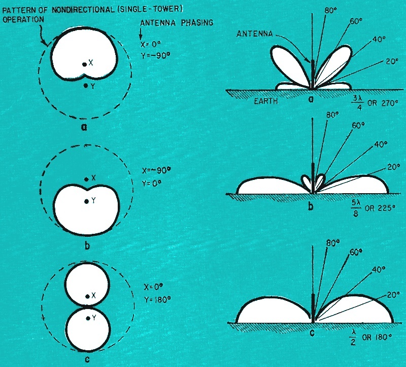
Fig. 1 - Horizontal radiation patterns of two vertical antennas spaced 1/4 wavelength and driven with phasings shown. By Ray D. Thrower, WA6PZR In Ham-band, CB and two-way communication, a fixed antenna has one disadvantage - it can't be turned. This means it's nondirectional and unless most of your communication is in one direction you pick up undesired signals along with the desired ones. The answer to this problem, of course, is a beam, so you can null out interfering stations and get more gain in the desired direction (or directions). Unfortunately, most low-frequency beams (80 or 160 meters) are large, expensive, and often objectionable to neighbors. Even at higher frequencies, beams are subject to mechanical problems, being exposed to the weather as they are. Rather than physically turning the antenna, why not do the same thing electrically? Broadcast and commercial two-way stations have been doing this for years. Recently even some TV receiving and CB antennas have appeared using the same principle. The system is called a directional array, and consists of two or more vertical radiators or elements. Spacing and phasing of the two radiators are adjusted so that the rf fields add in some compass headings (thus producing greater signal) and cancel in others (thus producing lesser signal). Basic DA Operation Fig. 1 shows three directional patterns you can obtain using two vertical radiators, a couple of hundred feet of transmission line, and some switches. Suppose you put up a tower or pole insulated from ground and used it as an antenna. The dashed-line circles in Fig. 1 show the pattern you'd get - a perfect nondirectional circle. Now suppose you put up another tower (you could actually use a flagpole or a telephone pole, and hang an insulated long wire off the side, just as long as the radiator is vertical). Space the second radiator 90 electrical degrees, or a quarter wavelength, away from the first.
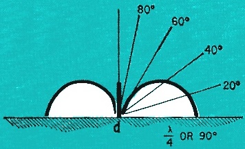
Fig. 2 - Vertical radiation patterns of vertical antennas of several heights.
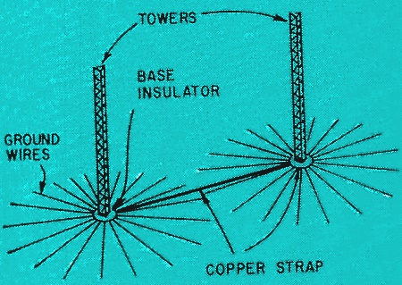
Fig. 3 - A fairly good ground system.
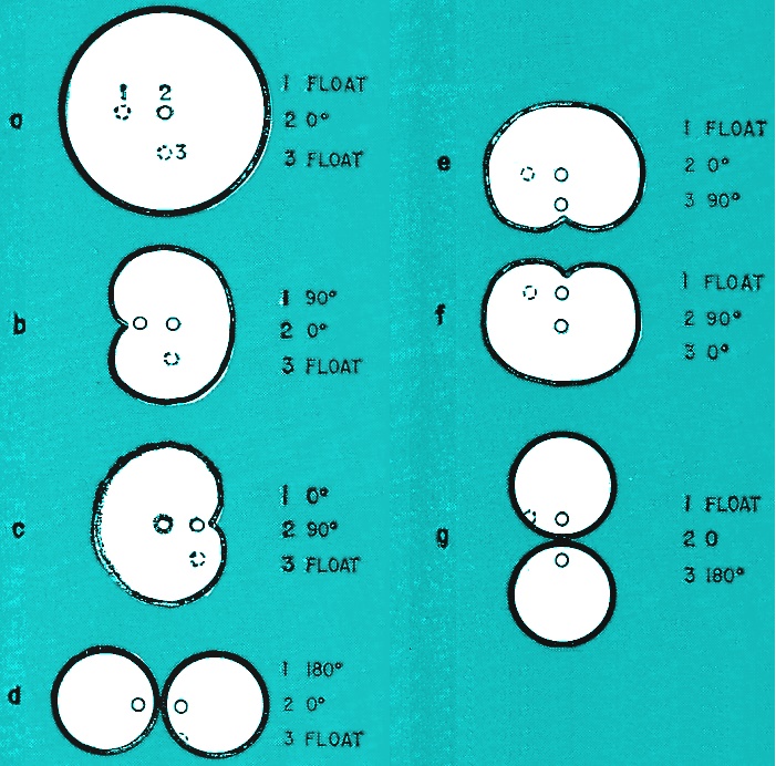
Fig. 4 - By using 3 towers in an L−shaped array, you get these 7 patterns.
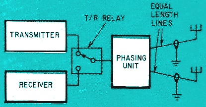
Fig. 5 - How to connect phasing unit.
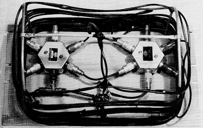
While this isn't the unit described in the text, it shows switch and cable placement.
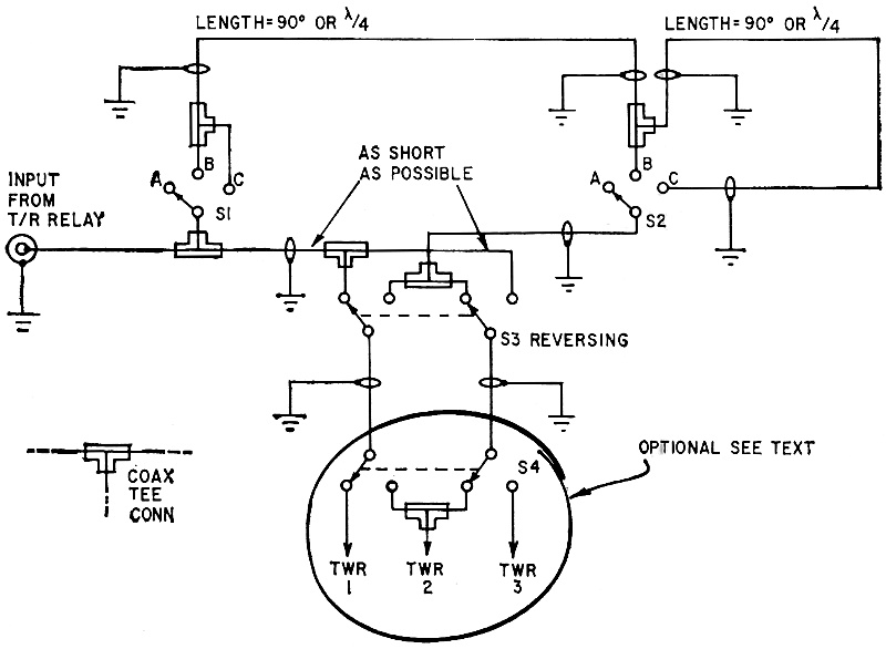
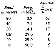
Fig. 6 - Interconnections inside phasing unit. All wiring must be coaxial cable. Parts List First tie the transmitter to the first tower (let's call it X). Now tie the second (Y) in parallel, but insert enough additional line to delay the rf by 90 electrical degrees. The pattern you get is shown in Fig. 1-a, a cardioid with a sharp null in one direction and a large lobe in the opposite. Reverse the phasing and you will reverse the pattern, as in Fig. 1-b. Add another 90° phase delay in the line to Y, or a total delay of 180°, and you'll have the pattern of Fig. 1-c, a bidirectional figure 8, with two sharp nulls at right angles to the lobes. These are the three basic patterns that will be most useful in nulling out undesired stations and copying desired ones. Antennas and Ground System There are steel or aluminum towers used for fringe-area TV reception which are reasonably priced and will do nicely as vertical radiators for low frequencies. For base insulators, you can buy ceramic cup types that electric power companies use on high-voltage line towers. You'll have to guy the towers, and break the guys with porcelain strain or egg insulators. Alternatively, you can put up telephone poles or flagpoles and hang an insulated wire off the side as a radiator. The two radiators should be equal in height. How high they are depends on how much money and guy space is available. Fig. 2 shows vertical-radiation patterns for four vertical radiators of four different heights, separately. At (a) a 270° tower has a great deal of high-angle radiation and only moderate ground-wave propagation. The 225° or 5/8-wave antenna at (b) has the theoretical maximum groundwave efficiency (good chiefly for local work, or long-hop DX), with only small lobes at skywave angles. The half-wave antenna of (c) has very little high-angle radiation and still a great deal of low-angle. Finally, the 90° or quarter-wave radiator of (d) is a fair compromise between high- and low-angle propagation. Since the shorter towers cost less, the quarter-wave is probably the best bet, and you may decide to make do with even less. Don't try anything less than a 45° or eighth-wave height, however; it will be so inefficient your time and money will be wasted. Such short antennas have low radiation resistances and ground-system losses take most of the rf power. They also have lots of reactance and are difficult to match to transmitters. The towers should be spaced 90 electrical degrees apart (a quarter wavelength). This is the best compromise between two undesirable extremes. Greater than 90° spacing produces a pattern with an increasing number of lobes and nulls. Closer than 90° spacing produces high mutual impedance between towers, which lowers radiation resistance and requires more rf driving current. Up go the losses and down goes the system efficiency. If you don't plan to put a good ground system in, then don't bother to put up the radiators at all. As I said before, you'll be wasting time and money. The radiation resistance of an antenna is what the rf works into. But in a vertical radiator the ground system is the electrical return - the other half of the circuit - so the ground-system resistance is in series with the radiation resistance of the antenna. A vertical radiator 54° (0.15 wavelength) in height has a radiation resistance of about 10 ohms. In Fig. 3 radial wires are laid in the ground extending outward from the base of each tower. Considering just one tower for a moment, if there are 120 radials each a quarter wavelength long, ground resistance will be about 1 ohm. Total system resistance is 11 ohms. If a 100-watt transmitter is connected, the ground system will take about 9 watts, leaving 91 watts for the antenna to radiate into space. Suppose the ground system consists of merely a piece of pipe driven into the ground at the base of the antenna. Ground resistance would be about 50 ohms, for a total of 60 ohms. Assuming the same 100-watt transmitter, the ground-system loss would be 83 watts, leaving only 17 watts for the antenna. If you can't afford to put a lot of copper into the ground, it's better to put shorter rather than fewer radials. Try for at least 15 or 20 equally spaced radials. Since you have few, they don't have to be so long - only about an eighth wave. Making them longer will have almost no effect. As Fig. 3 illustrates, bond the radials to a ring of copper strap around the base of each tower. Connect the shield of the transmission line to the ring. Use a section of strap between the towers to tie the wire ends where they overlap. Use another strap to connect the two base rings together. Radial wires may be buried a few inches in soil (not deeper, though) or left on the surface if there's no pedestrian traffic. Your operating frequency will determine the height of the antennas. For 160-meter (1.9-kHz) use, you'll probably want to use eighth-wave towers, about 65 feet high, since a quarter wavelength is 130 feet, and that kind of steel runs into money. Here are quarter wavelengths for other bands:
λ(ft)/4 = 246/f(MHz) At the higher frequencies - say from 27 MHz on up - it becomes quite simple to erect poles or tubular masts. Also, you can even use ground-plane antennas on a roof, but their operation will vary from those described here. This article concerns only vertical radiators with bases on the earth itself. Choosing Patterns Decide how many and what patterns you want, for this will determine how many towers you must erect. With two radiators, you'll be able to get four useful patterns (more are available, but hardly worth the trouble). Three are shown in Fig. 1. The fourth (not shown) is nondirectional, obtained by driving only a single tower. If you erect two radiators in a north-south line, signal lobes will be also north-south. How to get east-west lobes? Simple - put up a third radiator, making an L-shaped array, again using 90° spacing. By driving only two towers at a time you can shift patterns. Fig. 4 shows how. The Phasing Unit As Fig. 5 shows, the system for introducing phase delay is placed between the transmit-receive relay and the towers. The transmission lines from the phasing unit to the towers must be exactly equal in length, so no unwanted phase shift is introduced. Circuit connections are shown in Fig. 6. All switches are coaxial. S1 and S2 must be switched separately by hand and must always be in equal positions. As shown, S2 allows tower 2 to float, while S3 connects tower 1 to the direct line from the transmitter, for nondirectional operation. When S1-S2 are in position B, the first 90° delay line is put in series with the transmitter output and tower 2. This produces pattern C of Fig. 4. With S1-S2 in position C, both 90° sections of line are put in series with tower 2, producing pattern D of Fig. 4. S3 is used to reverse the cardioid pattern C to B. S4 is optional but necessary if a third tower is used. Tower 2 becomes the center radiator, while towers 1 and 3 are alternately floated by S4, thus changing pattern orientation from east-west to north-south. Components specified in the parts list will operate up to 1 kW and 100 MHz. Below about 150 watts and 5 MHz, you can save money by using RG-58/U and noncoaxial switches. After you've decided the operating frequency, compute the 90° length, with the wavelength mentioned earlier. As an example, for 3.9 MHz, 90° is 63 feet. Multiply this figure by the propagation constant of the coax you're using. This constant is found in many engineering handbooks and also in cable manufacturers' catalogs. For RG-8/U and RG-58/U the constant is 0.66. Thus 63 X 0.66 is 41.6, or about 41 1/2 feet. The photo shows a slightly different system, but illustrates parts placement on the back of the cabinet front panel. Bolt a frame of tubing to the panel as a cable support. After you've cut the lines and attached connectors form the cable into loops around the support frame and tape or lace them in position. Be sure to leave enough slack at the ends to reach switches and connectors. Don't force the coax into sharp bends or you'll change impedance and create a hot spot for arc-over, as well as increase standing-wave ratio. It's a good idea to place S1, S2 and S3 as close together as possible, so the coax between them can be very short. This prevents adding undesirable phase shift between radiators. Tuning the System Simply float tower 2, and load tower 1 to match your transmitter output as you normally would. Then reverse the procedure. One big advantage to using quarter-wave radiators is that reactance is practically zero. Radiation resistance of such a tower will be about 35 ohms. This is not a bad match to 50-ohm cable since the ground resistance will be in series, and will probably be 5 to 25 ohms. When both towers are being driven in parallel the total resistance will be half that of each. This means when switching from non-D (noridirectional) to DA (directional array) operation you'll have to retune the transmitter output. Of course, if you never use non-D the resistance will remain constant. Even in the three-tower array no more than two towers are used at a time. You can, of course, add compensation - a dummy load resistor to be switched in place of the floated tower. This cuts radiated power in half, though. Don't forget to use a lightning arrester at the base of each tower. Commercial models are available at parts houses. They are inserted into the feed-line at the antenna base. It's not a good idea to switch patterns while the transmitter's on the air, for you can cause voltage surges across switches that may damage them or the coax. Kill the high voltage when switching. In the receive mode you'll do no damage by switching. In fact, the system patterns are just as valid for receiving, and that's where you'll find the real value of this array. When you reverse a null, away goes an interfering signal! Have fun with your directional system.
Posted March 8, 2024 |
|
 Specify the center of the frequencies you operate
on and use the following formula to determine exact antenna height and spacing:
Specify the center of the frequencies you operate
on and use the following formula to determine exact antenna height and spacing: