Capacitors as Transducers
|
|
Capacitors have been used as transducers in one form or another since their electrical characteristics were first discovered. An electrical transducer is a device that converts some form of energy into an electrical signal. This transformation allows for the measurement, detection, or communication of various physical phenomena. There are various types of electrical transducers, each designed to convert specific types of physical quantities into electrical signals. Some common types of electrical transducers include: pressure, temperature, strain, light sensors, accelerometers, microphones, ultrasonic, magnetic, gas, and position and displacement. Back in the 1980s I worked as an electronics technician (pre-BSEE degree) for a company in Vergennes, Vermont, called Simmonds Precision Products. Their products were fuel measurement systems primarily for commercial and military aircraft. The sensors / transducers were capacitive in nature, consisting of coaxial tubes which stood vertically in the fuel tanks and used the fuel as a dielectric to vary the capacitance according to its ratio relative to air between the tubes. The transducers were positioned at strategic locations within the tank to provide an accurate measure of fuel regardless of the attitude and acceleration of the aircraft. Simmonds is now part of Collins Aerospace, after having been bought in 1983 by Hercules. Capacitors as Transducers -They can be made to count, measure and gauge.
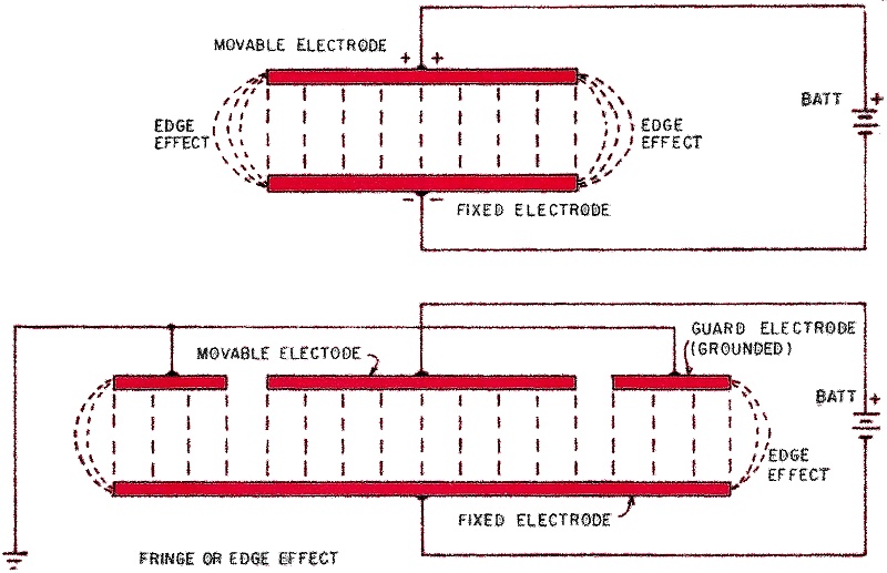
Fig. 3 - Edge-effect capacitance (top) is prevented by grounded guard electrodes.
by J. Merino Y Coronado* A capacitor is not just an electronic component wired into a circuit. Dozens of kinds of unusual capacitors are used in labs and along production lines throughout labs and industry. They count objects, gauge liquid levels or pressures, measure vibration or angles of rotation. Capacitors of this type are classified as capacitive transducers. A transducer is a device with two input terminals and two output terminals. It converts mechanical energy to electrical, or vice versa, according to a known law. It is reversible, which means that both the input and output are interchangeable. The cartridge in an inexpensive phonograph is a good example of a piezoelectric transducer: the mechanical vibrations of the needle are transmitted to a piezoelectric element (usually made of Rochelle salt or of a certain type of ceramic containing titanates). The element generates electrical charges when twisted by the movement of the needle. Conversely, if we put an alternating voltage across the cartridge, the crystal will produce vibrations and sound, which is a form of mechanical energy.
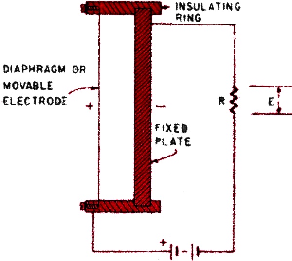
Fig. 1 - Common capacitive transducer is the capacitor (condenser) microphone.
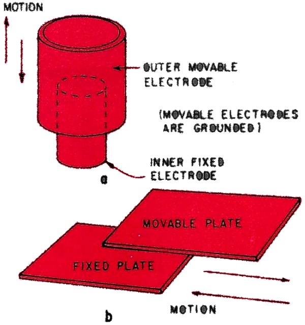
Fig. 2 - Two forms of displacement-measuring capacitors: (a) cylindrical; (b) plane. Moving element varies the capacitance by changing effective plate area.
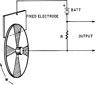
Fig. 4 - Variation of rotary meshing-plate variable capacitor is used to generate audio tones ... useful in electronic organs.
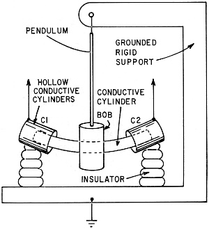
Fig. 5 - This capacitive pendulum can measure very small tilts or vibrations. Transducers are cylindrical type (Fig 2a).
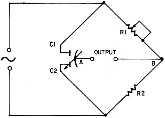
Fig. 6 - This ac bridge is detecting device for capacitive "tiltmeter" (Fig. 5). C1 and C2 are cylindrical transducers, changing voltage across A, B is amplified. The condenser microphone (Condenser is an old name for capacitor, which has persisted in conjunction with microphones.) is a capacitance transducer that transforms the mechanical energy of sound waves into electrical energy to operate an amplifier. In its simplest form it consists of a thick, fixed, circular metallic plate in front of which is a very thin conductive diaphragm separated from the plate by an insulating ring a few thousandths of an inch thick (Fig. 1). The diaphragm moves back and forth with the variations in air pressure caused by sound. As the distance between diaphragm and plate varies, the electrical capacitance of the microphone varies proportionally. A battery of usually 50 volts or more is connected to the plate and diaphragm in series with resistor R. An increase in capacitance allows the microphone to admit more electrons from the battery. A decrease forces some electrons from the mike back to the battery. As everyone knows, a flow of electrons is an electric current and this current produces (Ohm's law) a variable voltage (E) across resistor R. This voltage is applied to the grid of an amplifier tube or to a transistor. The condenser microphone is reversible. If an alternating voltage is applied between the diaphragm and plate in Fig. 1, the diaphragm will move accordingly, pushed by variations in electrostatic force, and, if the signal voltage is audio, a sound will be heard. This is the principle behind electrostatic loudspeakers. It is possible to increase the capacitance of a capacitor in three ways. Two are mechanical methods: increasing the area of the plates, or decreasing the distance between them. The first is used in rotary variable-tuning capacitors with meshing plates. The second is used in the compression-type of trimmer capacitor. Figure 2 shows two forms of capacitance transducer widely used for industrial and scientific purposes. In a we see a cylindrical configuration, in b, a flat or plane transducer. If one electrode is movable, both types produce a variation of capacitance linearly proportional to the amplitude of the movement (arrows). The capacitance of both transducers can be readily computed from the following formulas: For the cylindrical configuration we use: C(pF)= 0.644KLllog (b/a) in which L is the length in inches of the overlapping portions of the cylinders. The constant K is the dielectric constant of the material between the cylinders. The inner diameter of the outer cylinder is b, and a is the outer diameter of the inner cylinder, which is also in inches. For a capacitor made of two plane parallel plates the capacitance in picofarads is computed by C(pF) = 0.225 KA/D where A is the area in square inches of the portion of the movable plate which is actually over the fixed one, D is the distance in inches between the two plates, and K is, as before, the dielectric constant of the material between the plates. (For air it is very nearly 1.) Plane parallel plates and cylindrical capacitors are much used in industry and science to measure linear displacements. To measure angles of rotation, variable capacitors of the type found in radios are used, because their capacitance changes linearly with the angle, provided the rotor plates are semicircular and measurements are made between 15% and 85% of the rotation angle. There is a third way to change the capacitance of a capacitor: to change the dielectric. Oil, for instance, has a dielectric constant of 25.8. For distilled water the constant is 81.07. An air capacitor will have 25.8 times its capacitance when it is in alcohol, or 81.07 times its capacitance when submerged in distilled water. (Tap water cannot usually be used because the minerals dissolved in it make it too conductive.) Not all the capacitive transducers used for instrumentation purposes are built in the simple form shown in Fig. 2. The electrostatic lines of force at the edges of the plates or cylinders are not parallel, but bulge outward, producing stray capacitances that make the actual capacitance greater than the computed value. This edge effect or fringing must be kept to a minimum, since some transducers are made to measure capacitance variations of the order of 0.2 pF. This is accomplished by using a third, grounded electrode, called a guard ring or guard electrode. Fig. 3 shows the edge effect and how to eliminate it with a guard electrode for a capacitive transducer using plane plates, one of which moves either up and down or in and out, perpendicular to the plane of the paper. The arrangement is similar for cylindrical capacitive transducers. If the rotor shaft of a variable capacitor of the type used in ordinary radios is coupled to a rotating piece of machinery, rotation angles from 0° to some 150° can be measured. The coupling can be made to multiply the angle of rotation by a known factor - as by the use of gears, levers, or pulleys and strings. The transducer itself may have many forms. In most cases it has a guard electrode. Very small angles can be measured. A capacitive transducer used to generate audio tones works on the same principle as the condenser microphone. In Fig. 4, W is a wheel of Bakelite or any convenient insulating material. This wheel has sectors of aluminum foil connected to the shaft, which is grounded. In front of these is a fixed metallic plate or screw. As the wheel rotates, the capacitance between the conductive sectors and the fixed plate or screw varies and so does the charge. An alternating voltage appears across resistor R, with a frequency equal to the number of revolutions per second of the wheel multiplied by the number of sectors. This frequency can be amplified and measured with a frequency meter, and we have an electrostatic tachometer. The same principle is used to generate musical tones in some types of electronic organs. Measuring vibrations and tilting
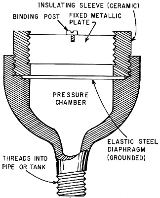
Fig. 7 - Pressure sensitive capacitive transducer (similar to condenser mike).
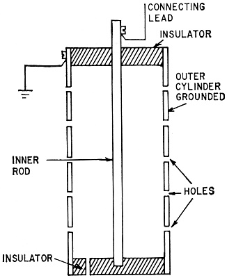
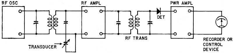
Fig. 8 - This device provides a continuous indication of liquid level without moving parts. Nonconductive liquids vary the capacitance between two electrodes. Capacitive transducers are much used in instruments for measuring vibrations caused by passing vehicles or heavy machinery, or tilting caused by heavy loads in bridges or buildings. The principle of a tilt meter or vibration meter is shown in Fig. 5. The bob of a pendulum carries a curved metal cylinder that moves in or out of two lateral hollow cylinders mounted on porcelain or Bakelite insulators. The two fixed cylinders and the grounded movable cylinder together make up a differential capacitor. If the pendulum support is tilted or otherwise set in motion, the capacitance between the pendulum and one of the other plates increases, while it decreases by the same amount be-tween the pendulum and the second fixed electrode. A simple ac bridge can be used to measure and record such variations. In Fig. 6, C1 and C2 are halves of the differential capacitor in a tilt or vibration meter. If R1 is adjusted so that the bridge is not balanced when the pendulum is at rest, an ac voltage is present between points A and B. This is called the carrier voltage, and it is amplitude-modulated when the pendulum moves. The modulated waves are amplified and detected in the usual way to be recorded or telemetered to another receiver. Guard electrodes are a must in this type of instrument. In Fig. 5 they are not shown for simplicity. Some time ago I designed and built a very sensitive seismograph using this principle. Capacitive pressure gauges When the indicator or recording device is at some distance, or when the pressure variations in pipelines carrying fluids are to be used for remote control, capacitance transducers are second to none. A pressure-sensitive transducer is shown in Fig. 7. It has a movable elastic metal diaphragm, grounded for obvious reasons. An insulating ceramic or porcelain sleeve holds a fixed conductive plate, strong enough to stand the full pipeline pressure in case the diaphragm fails. It is made quite stiff, with a resonant frequency of 10kHz or higher to reduce its response to vibrations or shock. The pressure gauge is nothing but a condenser microphone working at high pressures. Level measurement of liquids in tanks For this a simple cylindrical capacitor is used. The inner electrode is a rod or heavy metal cylinder, 1" or 2" in diameter. The outer electrode is a metal tube with holes in it, grounded to the tank (Fig. 8), while the inner rod is insulated. Nonconductive liquids cause the capacitance to increase according to their level and dielectric constant. For conductive liquids such as water or saline solutions, the inner rod is covered with plastic or any other type of convenient insulating material. A simple ac bridge measures capacitance variations, as described in Fig. 6. More elaborate devices are often used in these applications, such as the trf receiver that is shown in Fig. 9, to measure distance, rotation, pressure or liquid level in a tank. A very stable rf oscillator is coupled to a resonant input circuit in an rf amplifier. The capacitor of this tuned circuit is the capacitive transducer (in series or in parallel with a fixed or adjustable capacitor used for calibration or adjustment). A linear detector and power amplifier complete the instrument. Its output is used to operate a recording instrument or another controlled device of some kind.
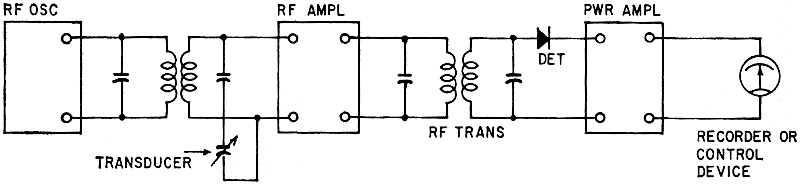
Fig. 9 - Tuned radio frequency (TRF) method uses capacitive transducer to generate amplitude, phase or frequency variation in rf carrier for detection, amplifying.
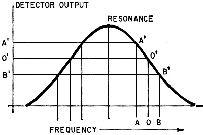
Fig. 10 - In slope detection, carrier is tuned to point 0. Capacitance changes may cause carrier shift to points A or B. The resonance curve of trf receivers is very much like Fig. 10. The "receiver" used to measure capacitance variations is never tuned to resonance, but to one side of the curve where its slope may be considered linear, let us say to the point marked 0 in the figure. The corresponding point, 0', is the operating point. An increase in capacitance from 0 to B displaces the operating point to B' and the output of the detector decreases. Very rapid variations in capacitance can be measured by this method. A phase-sensitive detector (Fig. 11) is used with capacitive transducers in many industrial and scientific instruments and applications. What about using a superhet? This more complex receiver is used to measure very small variations in capacitance. One grid of a mixer tube is fed by the output of a crystal-controlled oscillator, while the other is fed by a variable-frequency oscillator whose frequency is controlled by variations in capacitance caused by a capacitive transducer. In this way a variable i.f. is obtained. When both oscillators have the same frequency, the i.f. difference is zero. As soon as the capacitance of the transducer changes, the frequency of the variable oscillator shifts and an i.f. is produced in the mixer. Differences in frequency of a few hertz are easily detected by ear or by a frequency counter. R-E
Fig. 11 - Transducers C1 and C2 are used in phase-detector (discriminator) circuits.
* Research physicist and professor of acoustics and electronics, Institute of Geophysics and Polytechnic Institute of Mexico.
Posted August 30, 2023 |
|