Antenna Rotators
|
|
The purpose of directional antennas is not just to increase gain along a particular radial in order to enhance weak signals, but also to reduce gain in all other directions so as to minimize interference. Interference can be both signals from unrelated emitters and from multipath signals that originated from the same emitter. Hence, a directional antenna can be advantageous in an environment where a relatively strong signal from the intended emitter is surrounded by other strong signals. Even if the interfering signals are not on the same frequency, the effect of raising the overall noise floor and/or generating intermodulation products can degrade the intended signal significantly enough to bugger audio and/or video. The solution is to mount the receiving antenna on a rotator so that it can be pointed in a direction which results in the best signal. Here is my Alliance U-100 Tenna−Rotor write−up with photos. RCA is one of the few companies that still manufactures an antenna rotator of the type primarily intended for TV antennas. Many companies make models for Ham radio use. Antenna Rotators
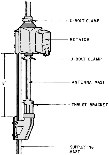
Fig. 1 - A thrust bracket is used to take the antenna load off the rotator.
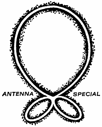
As antennas grow in size and increase in gain, the need for rotators also grows. Gain is inversely proportional to the width of the antenna's forward lobe. In other words, the greater the gain of a given antenna, the more likely the need for a rotator to pick up channels transmitted from different directions. The evolution of FM antennas is an excellent case in point. Before FM stereo became a fact, most people used nondirectional "flying S" or "turnstile" antennas. While gain was relatively low, these antennas picked up FM broadcasts from all directions, without the need of a rotator. FM stereo has changed all that. Not only are FM stereo signals weaker than monophonic, they are more susceptible to multi-path distortion. Thus, you need a very directional antenna with high gain for good FM stereo reception. But, if a number of stations are coming at you from different directions, you'll also need a rotator to pinpoint the incoming signals. Color TV is analogous to FM stereo. Ghosting - the TV equivalent of multipath distortion - is far more objectionable in color than in black-and-white. Color also requires stronger signals. In fact, if you mount a good directional antenna on a mast with a rotator, you'll find that color can be received only over a very narrow arc. You can swing the antenna many degrees to either side of the good color arc and still get excellent monochrome pictures. That is why you need a rotator to receive good color pictures. Antenna rotators can be used anytime you want to receive signals from a number of directions. Rotators, however, are not an unmixed blessing. For one thing, they complicate the antenna installation. For another, rotators present a problem in multi set installations. If Dad wants to watch the baseball game coming from one direction, and the kids want to watch cartoons transmitted from a station in the opposite direction, it's obvious that the rotator can't point the antenna in both directions simultaneously. One solution is to use two or more separate antennas, mounted on the same mast and combined by a hybrid splitter or coupler. Unfortunately, this can get to be even more expensive, complex and unwieldy than a rotator installation, in many areas.
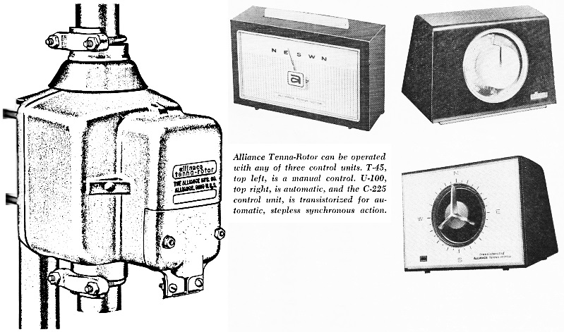
Alliance Tenna-Rotor can be operated with any of three control units, T-45, top left, is a manual control, V-100, top right, is automatic, and the C-225 control unit, is transistorized for automatic, step less synchronous action.
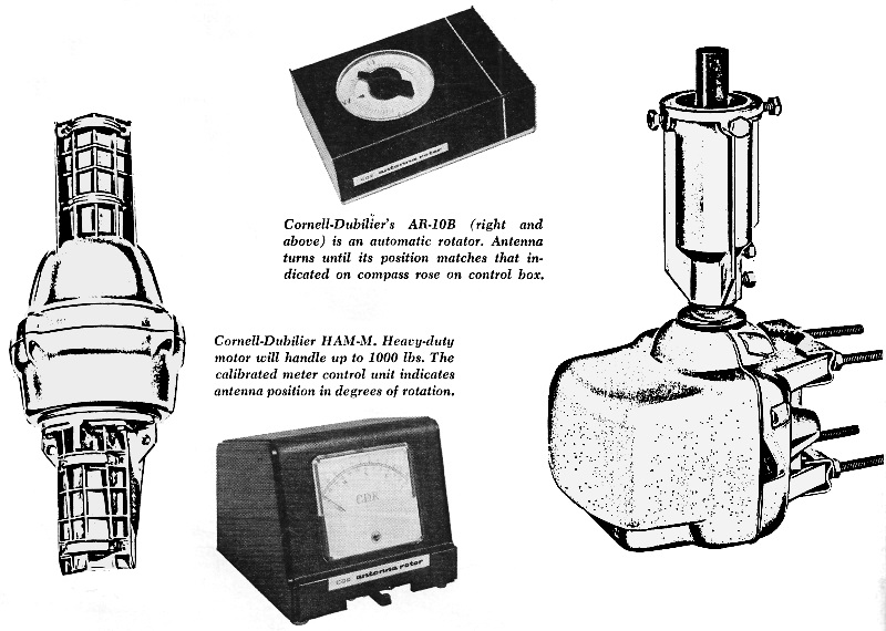
Cornell-Dubilier's AR-10B (right and above) is an automatic rotator. Antenna turns until its position matches that indicated on compass rose on control box. Cornell-Dubilier HAM-M. Heavy-duty motor will handle up to 1000 lbs. The calibrated meter control unit indicates antenna position in degrees of rotation. A rotator adds much weight to an antenna installation. Therefore the mast should be braced securely. For example, installers usually try to keep the mast short to make the installation as solid as possible. In a non-rotator installation, you can often use a 5-foot mast with nothing more than a chimney mount. However, the rotator adds both height and weight. Therefore, guy wires are recommended even for the simplest rotator installations. Use three or even four chimney straps rather than the usual two, and make sure the straps are rustproof stainless steel. Another good practice is to use a thrust bracket (see Fig. 1) in every rotator installation. The thrust bracket takes all the weight of the antenna, prolonging the life of the rotator. For safety and convenience, do as much as possible of your work on the ground. Chances are you can wire the rotator and mount it, along with the thrust bracket, before you even climb the ladder. You may also be able to attach the antenna to the rotator mast and the lead-in wire to the antenna, all on the ground. Once you do get up on the roof, be careful not to lose your balance. A big antenna on a high mast with a rotator is very heavy and cumbersome. It's a good idea to have a helper, especially on windy days. Try to keep the mast balanced and under control, with your feet planted firmly on the roof at all times. Inexperienced installers often have trouble with the rotator wires. It is easier to twist the leads and tin them before attaching them to the rotator terminals. This reduces the likelihood of stray wires shorting between terminals or touching the case. Also, if you use twin-lead, keep it away from the rotator wire. Some standoffs accommodate both rotator wire and twin-lead, but it is definitely bad practice to run these two cables closely in parallel. To avoid interference, tape the rotator wire directly to the mast. Use weatherproof vinyl tape, long standoffs for the twin-lead, and twist the twin-lead. Of course, if you use coaxial cable, interference pickup is no problem and the dual cable stand-offs will be convenient. Rotator Types The most common consists of a top-of-the-set control unit and a mast-mounted motor, connected by four- or five-conductor wires. One major difference between various rotators is the control unit. With manual control units, the user pushes a button or a bar and waits till the picture looks sharp. On automatic types, a knob can be set to a desired direction and the antenna will automatically aim in the direction indicated.
Posted June 6, 2023 |
|