"Snow Static" Being Beaten by "Flying Laboratory"
|
|
Triboelectric charging is the phenomenon whereby adhesion forces between two surfaces causes the dislodging of electrons from nearby atoms, with those electrons being attracted to the material with the highest positive potential as the interface attempts to neutralize itself. Relative contact motion (friction; e.g., walking across a carpet) is most often the cause of triboelectric charge transfer, but simply pulling apart two dissimilar surfaces can also be the mechanism (e.g., pulling a wool sweater off or lifting a polymer type fabric blanket away from a bed sheet) for charge transfer. Electrostatic discharge (ESD), a manifestation of triboelectric charging, can damage or destroy electronic components. Another effect caused by triboelectric charging is static in communications systems that are contained within moving vehicles like cars, boats, airplanes, rockets, etc. Much research has been performed to figure out how to mitigate the problem. By the late 1930s, radio static was inhibiting airborne communications to the point that serious action needed to be taken ... and it was. This story, the last of a three-part series, summarizes the findings and the remedies. One interesting aspect is the table that tells how a radio operator perceives static at various static voltage levels. "Snow Static" Being Beaten by "Flying Laboratory" This article has been presented here in order to show radio men contemplating aircraft-radio work as a livelihood some of the problems encountered in obtaining noise-free radio reception for increased flying safety. H. M. Hucke Part III
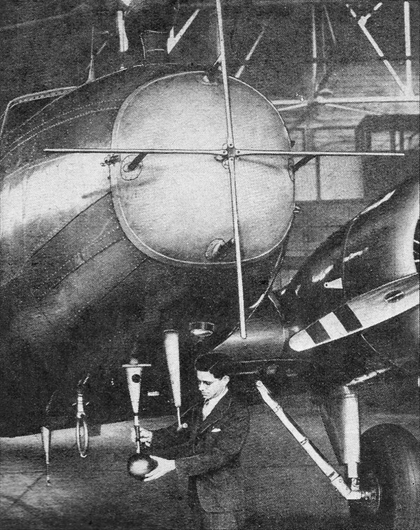
United Air Lines Communications Engineer H, M. Hucke under the nose of the company's "Flying Laboratory" with several of the experimental devices installed prior to flights to determine their efficiency in reducing static. Last Month the various effects noticed when different types of electrodes were placed .in the static field, of the "flying laboratory" during its many test flights, were discussed. Just how do these points now shape up with respect to each other? Initial Conclusions A grouping of these points suggested by Professor Starr gave the most orderly results. This group consisted of a pointed 2-ft. rod in the disturbed air at the tail; a pointed 2-ft. rod on the nose projecting into the undisturbed air ahead of the plane; and, a plate on the nose to record the impacting water particles. A study of our data on all the points has resulted in the following conclusions: (1) That the plane may be either positive or negative with respect to the surrounding cloud. (2) That at any instant one wing may be in positive cloud particles while other is in negative. (3) That at any instant the nose of the plane may be in positive particles while the tail is in negative or vice versa. The maximum cross-flow measured from wing-to-wing was about .500 microamperes though undoubtedly larger flows are possible. The maximum would constitute a stroke of lightning. There are many records of lightning strikes on all-metal planes which indicate wing-to-wing flows of several thousand amperes. During our flights we encountered one condition in a thundercloud in which the plane's magnetic compass moved 10 deg. with respect to the gyrocompass for a period of several minutes. This may have been due to a strong magnetic field in the cloud or to a cross-flow of current in the plane structure. Ground tests indicated that a wing-to-wing flow of about 45 D.C. amperes was required to produce the same compass deviation. A nose-to-tail current of 125 amperes produced the same effect, This would vary with the p6sition of the plane with respect to the earth's magnetic field. Further tests with special wing constructions are needed to establish the magnitude of current flow through the plane. Electric Charge is Due to 6 Variables It is known that a negatively-charged point will go into corona about 50 per cent more readily than a positively-charged point. It is also known that the action of the propeller in cutting up water particles at a top speed of 800 ft. per second will produce an electric charge. It is reasonable to believe that the wing of a plane moving at 260 ft. per second will break up water particles and produce a charge. The electric charge recordings are, therefore, the summation of at least the following 6 variables: (1) The plus or minus charges of the water particles in the cloud which are collected by the wing foil. (2) The generation of charge due to the wing sections splitting water particles. (3) The generation of charge due to the propeller splitting water particles. (4) Foreign matter in the water particles (Portland, Oregon, tap water split by the rotating propeller gives a positive charge while Cheyenne, Wyoming, tap water gives a negative charge). (5) The rectification action of the test points with different polarity of the plane charge. (6) Cross-current flows due to the plane short-circuiting sections of cloud having different potentials. From the above it is obvious that the mechanism by which the plane gathers an electrostatic charge is quite complex. Rather than spend valuable flight time trying to reach an orderly conclusion from this group of variables, it was believed best to proceed on to possible solution. In any case, it appeared probable that whether the plane became plus or minus it eventually reached a sufficiently high potential for corona discharges to appear on wing tips or any sharp projecting points. As a check on this assumption a tracing oscillograph connected to any of the test points gave typical corona discharge tracings whenever the characteristic sounds were heard in the plane's radio set. Charging the Plane to 100,000 Volts The plane was charged up by a small Wimshurst machine while standing on the ground and by bringing a pointed ground wire near its structure, the characteristic snow-static sounds could be duplicated. Since this experiment was limited by (1) the insulation of the rubber tires, (2) the A.C. modulation of the Wimshurst disc, and (3) the general variability of such a generator, a more substantial arrangement was desirable. Through the courtesy of the Westinghouse Company and Stanford university, we were able to borrow high-voltage insulators and assemble a 100,000 volt D.C. ray power supply. The plane was set up on these insulators in a large metal hangar and charged up to either plus or minus 100,000 V. With this arrangement engineers could remain inside the all-metal plane with all radio equipment operating and use the test equipment in the same manner as was possible in flight. The tests further substantiated the corona discharge theory. The power was sufficient to make the anti-static loops and regular antennas inoperative in the same general ratio as had been observed on the test flights. The characteristic snow-static sounds were present. Source of "Crying" Snow-Static. Static noise in the receivers with regular antennas began as low as 30,000 V., depending upon local humidity and the proximity of the artificial ground plane to the various points on the plane. The "crying" snow-static sounds usually began at about 55,000 V. and occurred more readily when the plane was positive with respect to ground. This crying phenomenon was readily traced to a corona discharge from some point on the plane. Artificial points were set up for its study and we concluded that the space charge in the ionized air around the point breaks down at an audio-frequency rate. This rate varies with the amount of moisture in the air and the voltage gradient at the point. Under controlled conditions it will produce any audio-frequency note. For example, on one test the nose produced followed the order shown in Table I. Table I Voltage Characteristic Sound 55,000 noise like frying bacon 60,000 frying noise begins to pulse at about 10 cycles per second 62,000 frying noise pulses at 100 cycles 64,000 frying noise pulses at 500 cycles 66,000 frying noise pulses at 2,000 cycles 68,000 frying noise pulses at 8,000 cycles 70,000 frying noise pulses at 15,000 cycles 72,000 frying noise pulses at above audibility At about this point some other point on the plane begins the same sounds and goes on up through the musical scale. At any one time it will be possible for a number of points to produce this musical corona in any order. This, then, is the cause of the characteristic snow-static sound. A study of the plane structure indicates that antenna masts, rivet heads, cotter keys, on aileron hinges and tail wheels, the antennas themselves and any sharp points on the plane are the focal points of the corona discharges and consequently the source of snow-static radio interference while in flight. Unless these discharge points are quieted snow-static cannot be eliminated. Covering them with an insulator, reducing their sharpness, or covering them with a well-rounded corona shield will only allow the plane to build up to a still higher potential until some other point starts corona. There are two solutions open: (1) reduce the ability of the plane to gather or generate charges; and (2), admit that the plane cannot be prevented from gathering charges and work out a means for discharging it which will not cause radio interference. The second solution offered the best possibilities although several plans for accomplishing the first will shortly be tested. It is probable that a partial solution of both will eventually be used. Suppressor Resistors Help Reduce Static Effects A study of the noise indicates that it has a very short wavelength and that its attenuation with distance is rapid. The field pattern caused by a point in the corona at the rear of the airplane is shown in Fig. 1. Note how the area of interference production is continuous with the trailing edges of the airplane. When a resistor was added in series with the point the interference was materially reduced by a change in the noise field pattern to a location in the rear of the airplane and comparatively isolated from it, as illustrated in the lower portion of the diagram. Curves run on resistors indicate that at least 100,000 ohms and in some cases up to 10 megohms are necessary. Moving the point away from the plane takes advantage of the rapid attenuation and gives a better pattern. This indicated that a trailing discharging point as far as possible behind the plane with suitable suppressor resistors had possibilities for discharging the plane. Up to 1 milliampere discharge at 50 ft. could be obtained with 100,000 V. without disturbance in the radio set using the regular antenna. A 25 microampere discharge from a point without suppressors 2 ft. from the plane prevented radio reception! Since the mechanical troubles of a trailing wire are not desirable a second version of this idea was tried. Here a series of 17 3-ft., 3/1,000- in. dia. wires having a 5-megohm resistor in each was attached to suitable points on the wing and tail surfaces. Test flights of these dischargers are still in progress. Results in the air have verified the test made on the ground. The single trailing wire appears superior to the individual short wires though tests are not yet conclusive. The dischargers are still considerably short of a commercial cure and to date will only clear up radio range reception in about 15 per cent of the conditions encountered. Apparently the rate of discharge is not yet fast enough when the plane enters areas where the water particles have too high a potential. Although this system is not yet commercially practical, we feel that it is the first step on the road to a final solution. Anti-Static Aircraft Antennas
Fig. 1 - Resistors remove noise-field from plane. Our antenna tests indicate that snow-static interference is considerably worse at the rear than at the front of a plane. When the snow-static noise was of average strength, the loop located in the tear drop housing and the loop on the belly were both rotated and indicated that the source of maximum disturbance was toward the rear of the plane. When the static became extreme, rotating the loops indicated static in all directions. Probably corona had started on the wing tips and propellers in conditions of severe static. In mild snow-static when beacon reception on the "V" antenna was normal, the 2 rear beacon antennas were so noisy that no beacon reception was possible. The vertical rear antenna had a 25 to 1 better signal pick-up due to polarization of the range signals, but the snow-static pick-up was about the same on either. Both rear beacon antennas were about the same length and spacing from the fuselage. We concluded that the snow-static interference radiation was not normally polarized. Although the 40 ft. top antenna was far superior to the lower "V" antenna, from a signal pick-up standpoint, in snow-static the "V" antenna would pick up 5,000 kc. short-wave stations 1,000 miles away when they were unreadable on the top antenna. Although we did not test a trailing wire as an antenna, we did conclude from our study that it should be about the worst form of antenna for reception in snow-static. It would carry as high as 2 milliamperes of discharge current in vigorous "warm front" conditions. The static leak connected across the input of the average receiver is about 1/2-megohm; with a 2 ma. peak current the voltage drop across the antenna input circuit of the receiver could be 1,000 V. The noise modulation on this D.C. voltage would be less than 1%, or only a few volts of random A.C. During the tests we reeled out 150 ft. of steel No. 14 B. & S. stranded aircraft cable. It had no resistance suppressors in it and did not increase or decrease snow-static on the beacon frequencies. The short-wave receiver, however, was tuned to a 60 meter wavelength, hence, the 150 ft. cable plus the 65 ft. plane length was more than one wavelength long. Reeling the cable in and out gave 2 nodes of maximum snow-static and 2 nodes of minimum snow-static. The minimum, however, was not sufficiently low to materially aid reception. Insulated Antennas At the time we began our tests there were some snow-static theories which presumed that the noise was due to charged particles striking the antenna. To check this, a special pair of rod antennas were constructed. These were hollow, 1 in. dia. tubes of bakelite and the other of aluminum. The single wire antenna was held in the center of these tubes by insulating discs and the lead-in completely enclosed in metal tubing. With this arrangement no particle of any kind could strike the antenna itself. The aluminum tube was grounded to the plane at 3 points with 1/10-meg. resistors. The bakelite tube was painted with a solution of airplane dope and graphite so that its entire surface was a 10,000-ohm resistance leak to the plane. Good beacon reception was obtained on either antenna, but they gave no advantage over the regular No. 14 bare copper wire antenna exposed to the snow and rain particles. We concluded that the impinging particles were not sources of noise, or that the corona noise was so great that the impinging particle noise was obscured. In conditions when the plane is highly charged and corona appears as St. Elmos' Fire at the propeller tips, the regular bare No. 14 antenna wires must also go into corona. Since the wires have a small diameter they might discharge to the atmosphere sooner than other points on the plane. To test this, the "V" beacon antenna was replaced with wires having a diameter from 3/1,000-in. up to 1 in. dia. tubing. As the diameter increased, the reception improved and the outgoing corona current decreased. The curves indicate, however, that only a very small advantage would be gained by increasing the present wire diameter from No. 14 to No. 10. It is of material importance to reduce all sharp points such as cotter keys on antenna fittings, and to generally round off all rough edges on antenna structures. Horizontal and Vertical Dipoles A pair of horizontal and vertical dipole antennas was tried on the ground with the 100,000 V charging equipment. They were tuned and coupled to the receiver by means of an electrostatically shielded antenna transformer. Although "they gave a definite improvement over corona static as compared to a single bare wire, their signal pick-up was too poor for practical aircraft use. Resonating the aluminum tube antenna previously discussed, gave some gain against corona static, but not enough to warrant its use. Under the same conditions, a receiver having a high-impedance antenna coupling system was compared with another receiver having a low-impedance antenna coupling system. The corona static to signal ratio was practically identical on both receivers. The metallically covered loop antennas gave the following advantages over the regular bare wire beacon antennas: (1) The advantage varies with the intensity of the corona discharge. (2) In mild snow-static the advantage as measured by R.M.S. static output of the receiver may be 20 or 30 to 1. (3) In heavy snow-static the advantage drops to 5 or 10 to 1. (4) In very heavy snow-static no range reception can be heard on any loop antenna even when flying within 2 or 3 miles of the range station. On one test trip in a Pacific tropical-marine, warm air mass front no range reception was possible when any of the anti-static loops were used for a period of 25 minutes. Had we remained in this air mass layer we could have been without range reception for several hours, since the front was parallel to the airway. With the assistance of our meteorologists such conditions can normally be avoided, and this particular flight represents an extreme case. It does appear, however, that the anti-static loops must be coordinated with discharging systems and meteorological guidance if a complete solution is to be obtained. It seems that the advantage of the metallically shielded loops lies in their metal covering. An experimental, wooden nose was installed on the plane, and covered with copper foil. The foil was cut at suitable points to make a Faraday shield. An unshielded loop in this nose gave practically the same results as the loops with the metal immediately surrounding the wire. The loop in the tear drop housing gave practically the same results as the nose ring or metallically covered loop on the plane belly. The nose ring loop was usually about 5 per cent better than the loop on the plane belly, probably because it was farther forward. A low-impedance metallic loop with an impedance-matching network gave the same results as a high impedance of the same metallically covered construction. The wooden nose without cooper foil was painted with a mixture of dope and graphite so that it had an average resistance of 20,000 ohms to the plane structure. Signal pick-up dropped about 15 per cent for loops inside this nose. No change in snow-static advantage occurred. An unshielded loop in this nose suffered from snow-static, while a metallically covered loop in the same place gave the usual advantage. Position about the nose of the plane seemed to have very little bearing on the snow-static effects. Miscellaneous Sources of Static Any insulated surfaces such as windshield, de-icers and non-metallic loop housings can charge up with respect to the plane. When the charge on them becomes high and the plane suddenly flies into a higher or lower charged cloud area, these insulated surfaces will spark to the plane structure. Painting the loop housing with dope and graphite stops this source of noise. If, however, the plane flies through an icing area, an ice cap will form on top of the graphite paint. This ice cap is an insulator which charges up and sparks over in the same manner as the insulated surface. Thus in ice, the special paint does not accomplish its purpose. The answer is to streamline loop housings so that ice does not form. For some time we have been using bakelite stubs instead of the egg-type insulators on transmitting antennas to avoid ice troubles. These stubs have always followed the usual streamline form with the blunt forward edge and tapering rear edge. They also gather a thick layer of ice on the blunt forward edge. As a result of our loop housing work, we are now constructing stubs with a sharp front edge, which should completely and finally solve the antenna icing problem. During the course of our flights we found that the bonding on one of the ring cowls had broken. This ring cowl, resting on leather pads, charged up in snow-static and sparked over at regular intervals. In average charged clouds, this sparking caused a headphone noise sounding like pebbles falling in a metal pail. Any other exposed metal parts on a plane which are not bonded would cause a similar noise. The first steps toward improving plane reception in snow-static should include a thorough inspection of all bonding. Our work with the loops gave rise to considerable speculation as to why a shielded loop attenuated the corona radiation and an unshielded loop did not. Four theories have been advanced, but none have been carried far enough to date to warrant discussion here. All, however, must consider that the wave front of the interference is exceedingly steep as compared to that of the beacon signal. Dr. O'Day is working on a mathematical approach to the problem, which we hope will clear up this peculiarity. Once it is understood, the way may be open to a new type of antenna which does not have the disadvantages of the loop. The loop type of beacon antenna has no cone of silence, and is practically "unflyable" when within 5 miles of a loop-type DOC radio range. To overcome this, we might assume that we can always change over to the regular antenna when close to the station so that a normal cone of silence can be obtained. It is assumed that the range signal will override the snow-static when close in. Actually, however, we have records of a number of cases where the static directly over the range station was strong enough to make changing over impossible since even the loop unable to receive through the static. In closing this paper, I wish to express our appreciation of the assistance, advice and loan of equipment which made this work possible. A number of men gave of their time without compensation, and the manufacturers their personnel and equipment without hope of remuneration. The author of this article on the problem of snow static as it affects aircraft-radio reception, and discussion of methods being developed to counteract snow static, is Supt. of Communications Laboratory, United Air Lines. The subject matter of this series of articles was recently presented at Denver, Colo., before the Inst. of Aeronautical Science, and the American Assoc. for the Advancement of Science.
Posted August 25, 2021 |
|