The Skin Effect Talking Lightbeam
|
|
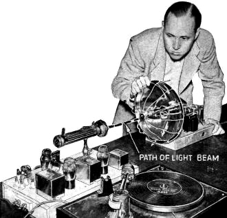
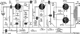
Modulating a light beam for secure communications was not a new concept is 1939 when Gerald Mosteller invented his device, but doing so with inexpensive equipment, using "outside-the-box" thinking, was new. Exploiting the relatively recently discovered physical phenomenon of "skin effect," his system used a specific range of frequencies to modulate the filament of a standard flashlight type incandescent light bulb that could effect temperature changes - and therefore intensity changes - rapidly and of significant amplitude to transmit information in the audio frequency range. Mr. Mosteller's contraption evolved as the result of a college thesis project. There does not exist a plethora of modern-day modulated light communications systems using incandescent bulbs as the source, so it is safe to assume insurmountable physical and/or financial obstacles prevented it from going mainstream. There are, of course, many modulated light communication devices in use, but primarily at infrared and ultraviolet wavelengths. The Skin Effect Talking Lightbeam Gerald Mosteller, University of Southern California graduate, is shown with a portion of his apparatus for sending sound over a lightbeam, using an ordinary 5-cent flashlight bulb and simplified radio parts. His discovery formed the thesis for his Master's degree at the University. By Gerald Mosteller The University of Southern California has cooperated in making available to Radio-Craft readers this first detailed description of the principle and equipment comprising the "skin-effect" lightbeam telephone discovery of a U. of S. C. graduate. Anyone can easily duplicate Mr. Mosteller's experiment. A new means of transmitting sound over a beam of light by use of amplifiers and an ordinary 5-cent flashlight bulb constituted the writer's thesis, for his Master's degree at the University of Southern California last June. This simplified form of sending music, voice and other sounds over a lightbeam, discovered during studies in Physics, has been the subject of experiments by scientific laboratories over the country with expensive equipment for a period of years. Its use in secret communication by the army and navy, landing of airplanes with lights that penetrate fog, and adaptability by automobile races in communicating with their pits, are given among possibilities. In contrast to radio communications, messages cannot be intercepted except by instruments set up directly in the beam of light. By using infra-red filters an invisible beam can be created which further prevents interception. How it Works By means of a radio-frequency oscillator and equipment similar to that of the ordinary home radio set, sound is amplified and the output caused to modulate the oscillator. A "skin effect" is created on the surface of the light filament and instead of heating the entire filament as heretofore, the current travels along the surface . Thus the filament may change temperature fast enough to transmit sound. Skin Effect The receiver consists of a photoelectric cell "detector" followed by 3 stages of A.F. amplification. Condenser C1 and resistors R3 and R4 are mounted directly behind the P.E. cell in the reflector. The transmitter consists of a speech amplifier, oscillator and ordinary flashlight bulb. The A.F.-modulated current flows along the surface of the filament (skin-effect) causing rapid fluctuations of the light intensity (which, in turn, are translated into intelligibility by the receiver). Skin effect is a phenomena of alternating currents. The maximum inductive reactance in a wire or filament is at its axis. In general the inductance offered to other filaments of current decreases as the distance from the axis increases. Thus the current is distributed so that it is greatest near the surface. The heat generated by this current is proportional to the square of the current. The heat is radiated from the surface, conducted to the cooler center and used in raising the temperature of the filament. The high-frequency alternating current (radio-frequency) causes the skin effect, the modulation of this current varies the surface temperature of the filament so that the light varies with the modulation. The conductivity of the metal carries the surface heat toward the center of the filament when the modulated current is great, thus allowing the surface to cool more rapidly so the radiation may follow the modulated current down. This improves the audio response at high frequencies. A curve was drawn to show the advantage due to skin effect. It was shown as a percentage of the oscilloscope readings of a sine wave at some frequency compared with the reading at 768 cycles per second. This curve of the efficiency of lightbeam modulation was measured on an oscilloscope having its vertical sweep connected to the output of the receiver. The input to the oscilloscope was a beat-note oscillator connected to the transmitter.A photoelectric cell is mounted in the focus of a parabolic reflector which may be made from an electric heater by removing the heating element. The particular heater purchased was selected after testing several because it concentrated rays from a distant light at a very small area. It is necessary that the rays focused by the parabola form a sharp-pointed cone of light which can get into the curved plate of the cell rather than hit on its outside edge. Directly behind the cell is mounted a midget 0.01-mf. coupling condenser, C1; a 1-meg. resistor, R3, through which the cell receives its positive voltage and the 5-meg. resistor, R4, which is the grid resistor for the 1st tube. The shielding afforded by the metal reflector and the wire shield in front of it is enough for shielding these elements, however they might be further shielded to cut down A.C. hum by wrapping them in tinfoil and grounding the foil. Similar phenomena have been developed before by means of high-voltage equipment and the use of cathode-ray and neon lights, but never before with simple equipment including the use of a "nickel" (5c) battery lamp. The 12-meter grid coil is wound with 18 turns of No. 14 enamel-covered wire on an air core 2 x 1/2-in. inside dia. The 12-meter plate coil has 12 turns of E.C. wire on a 1 1/2 x 3/4-in. dia. air core; the coupling to the Mazda-lamp circuit is accomplished by means of a single turn of No. 14 E.C. wire around the center of the plate coil. One position of the S.P.D.T. switch connects the mike through a 4 1/2 V. mike battery, the other cuts the battery out so a low-impedance phono pickup may be used. The single-button carbon mike used had low impedance. List of Parts Transmitter
Receiver
Posted August 8, 2023 |
|


