Simple Radio Mathematics for the Service Man
|
|
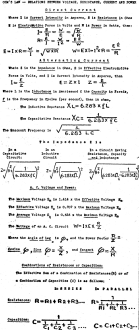
Included in this first of a series of the "Simple Mathematics for the Serviceman" articles that ran in Radio-Craft magazine is another "cheat sheet" full of oft-used formulas. It begins with basic Ohm's law, resistance, inductance, and capacitance, then builds from there. What was valid in 1930 is still valid in 2022. See the October 1930 issue for the next installment that includes yet another handy-dandy cheat sheet of formulas. A couple examples are given. Simple Radio Mathematics for the Service Man It is generally believed that mathematics is a highly complicated science and that formulas, being mathematical expressions, are equally involved and complicated. There are consequently many radio men who have acquired a deep-rooted, though not very wise, aversion toward the mathematical end of the radio science. They may be termed "formula shy." However, there is no royal road to knowledge, and, since radio is a mathematical science, the amateur and, particularly, the professional Service Man must admit that, without a thorough knowledge of at least the basic formula, he is "licked." This article is intended primarily for Service Men who take their calling seriously. It comprises a discussion of formulas most commonly encountered or useful in the radio shop or practical laboratory. These are tabulated also in a form that permits quick and convenient reference. Use this table as you would a vacuum-tube chart. The intelligent Service Man does not attempt to memorize all the facts found in the conventional tube chart. He first learns how to use it; he determines what information the chart contains that may be of interest to him. Thus, when a question presents itself, he knows that the tube chart contains the answer; and he consults it as frequently as he may find desirable. Follow the same procedure with the formulas given. Of course, first read this article carefully and familiarize yourself with the possibilities for more intelligent and efficient application of theory to practice. Post the table where it can be consulted when need be; better yet paste it on a stiff cardboard and tack it to the wall of your workshop. While it is not recommended that all the data be memorized outright, those who apply a little effort will be rewarded by a thorough knowledge of the formulas presented and as time goes on will actually know them by heart. To begin with, let us understand that a formula is nothing but a statement of fact or facts. It is, of course, expressed in symbols and invariably is the most concise statement of the fact or facts it deals with. Current, Resistance, Voltage Let us consider Ohm's Law - the most fundamental of all electrical formulas.
This law is basic, and finds application wherever potentials or voltages are involved.
It is one of the few formulas that the Service Man should memorize outright. The
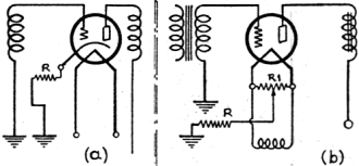
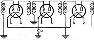
basic form of Ohm's Law is The first modification of Ohm's Law tells us that the voltage drop across any two points of a circuit is proportional to just two factors; current and resistance. Fig. 1 - In either circuit, multiplying the plate current of the tube by the value of the cathode - (filament-) return resistor gives the grid bias. Fig. 2 - The rule is the same here, except that the current of more than one tube passes through R. The sum of their currents is therefore used. Fig. 3 - While the voltage drop across any resistance in a circuit is equal to its value multiplied by the current passed, the wattage (which measures the heat generated) is equal to the resistance times the square of the current. Different wattage ratings may be necessary in a series of resistors. Thus this formula is particularly useful in the workshop. In Fig. 1, two extensively-used methods of obtaining "C" bias by the voltage
drop across a resistor are shown. In practical service work, it is often desirable
to determine what value of resistor to use, in order to obtain the desired value
of biasing potential. For this calculation, the third modification of Ohm's Law
is employed. In using the formula In the practical application of Ohm's Law in any of the basic forms, it should be understood that it can be applied equally well to the whole circuit or to any definite portion of a circuit. Care must be exercised that the known values are those of that particular section of the circuit, and not those of the entire circuit. Fig. 3 illustrates this point graphically. Wattage Formulas In electrical circuits it is not sufficient to know that, for a given purpose
a resistor of a certain ohmage must be employed. We must also know what wattage
rating the resistor must have, in order to carry safely the required current. The
wattage may be easily determined from the expression
It is quite customary, in radio design, to employ resistors of a wattage rating several times greater than the calculations call for. This is a precaution against resistor burn-outs, where facilities for ventilation, are poor and the danger of burnout through overheating is correspondingly high. The above formulas are fundamental in radio work, and the Service Man who preserves them for reference will find them frequently useful. The wattage rating of a resistor applies to the entire resistor only, and not to any section of the resistor. It is apparent that, in order to pass a certain amount "of current through a given resistor of definite resistance and wattage, it is necessary to apply a certain definite potential across the resistor. If this potential, however, is applied across a section of the unit, the decrease in the resistance will cause a corresponding increase in the current, through the section employed, which will naturally be beyond the permissible safe value and the useful life of that particular section will be materially shortened if not suddenly terminated. Thus wattage ratings of units are applicable to the entire units only, and not to any section of them. Commercial resistors are commonly marked as follows: "1,000 ohms - 10 watts."
It is frequently desirable to determine from such a rating the value of current
that may be safely passed through the resistor without overloading. This (1/10-ampere,
in the instance above) is obtained from the relation
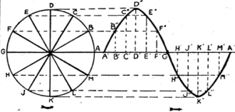
Series and Parallel Circuits We need not devote much space to the formulas devoted to the determination of the resultant value of a combination of resistors or condensers, in series or in parallel. The formulas themselves are quite clear and require no special explanation. The wattage of the individual resistors is not affected by the series connection. It is clear, therefore, that the resulting resistor, consisting of several resistances in series, should not be permitted to carry more current than is permissible for the resistor of the series having the lowest wattage rating. When two or more resistors are connected in parallel, the resultant value of resistance is less than that of the smallest of the resistors used in the parallel connection. While the current-carrying capacity of the individual resistors remains unaffected the current permitted to pass through the parallel circuit may be as great as the sum of the current-carrying capacities of the individual resistors. With regard to condensers, when two or more are connected in parallel, the resultant capacity is the sum of the individual capacities. When two or more condensers, however, are connected in series, the resultant capacity is smaller than the smallest of the individual capacities used in the series arrangement. Condensers of the higher capacities are, as a rule, rated for their working voltage. When voltages in excess of the rating are applied across the terminals of anyone condenser its useful life is materially shortened, and, if the excess is great, its usefulness may be instantly terminated. The question naturally presents itself, how this working voltage of the individual condensers is affected when two or more of them are connected either in series or in parallel. For a parallel connection, the voltage impressed across the parallel bank should not exceed the voltage rating of the condenser having the lowest working voltage rating in the parallel circuit. When condensers are connected in a series circuit the voltage applied across the entire series may be greater than the working voltage specified for the individual condensers. When all of the individual condensers are of equal capacity and of equal voltage rating we may apply across the series a voltage equal to the sum of the individual working voltages. The above is correct only if the D.C. resistances of the condensers are of like value. Such a. condition very seldom obtains in practice and, in order to prevent uneven distribution of voltage, a resistor of 100,000 ohms is customarily shunted across each individual condenser of the series. This shunt resistance is sufficiently great and can not interfere with the normal functions of the condensers. When the condensers in the series are of unequal capacities, the voltage distribution is uneven; being affected by difference of capacity as well as by difference in the D.C. resistance of the individual condensers. Voltages Across Condensers Ignoring the effect of D.C. resistance it may be stated, with sufficient accuracy (especially where a reasonable factor of safety is allowed), that the voltage across the individual condensers in the series is inversely proportional to their capacities. The smallest of the condensers will have the highest voltage drop across its terminals. Thus if we have connected in series three filter condensers rated as follows - 2 mf. - 350 volts; 3 mf. - 350 volts; 4 mf. - 350 volts - and the voltage impressed across the series is 900 volts, the 4-mf. condenser will have approximately 225 volts drop through it. The 3-mf. condenser will have approximately 300 volts; and the 2-mf. condenser, approximately 450 volts. It can be seen at once that the 2-mf. 350-volt condenser is not suitable for the series; since the voltage drop through it is considerably greater than the specified working voltage, It is frequently asked why it is that the A.C. rating of a condenser is lower than its D.C. rating. The explanation lies in the nature of alternating current, which does not possess the steady characteristics of direct current. The form of alternating current, usually assumed in A.C. theory is that of a "sine curve," shown in Fig. 4. It is apparent, then, that the value of either current or voltage in an A.C. circuit is continually changing; assuming successively all values from its positive maximum to its negative maximum. A vacuum-tube voltmeter indicates the maximum or peak values of an alternating voltage. A.C. voltmeters and ammeters, however, indicate the effective values; which, as the formula chart shows, are equal to only 0.707 of the maximum values. Fig. 4 - The familiar "wave-form" at the right is not the picture of a real wave; it is merely a spreading out of the circle at the left, so that the time of each current value can be measured along the base line, instead of in an angle around the center of the circle. A.C. voltages or currents generally employed are the effective or "root-mean-square" (R.M.S.) values. Thus, if an electric receiver is said to operate from 110 volts A.C., the effective value is referred to. Similarly, if a condenser is rated for 300 volts A.C., the effective value is meant. The very same condenser is probably rated for 450 volts D.C. The peak value of A.C. that may be impressed upon the condenser is also approximately 450 volts. Thus the A.C. voltage rating of a condenser is lower than its D.C. rating because the A.C. rating is in effective, and not maximum, value. If the maximum value were used for A.C. condenser rating, it would be of the same value as the D.C. rating. If a condenser is rated for direct current only, and it is desired to determine the A.C. rating by calculation, assume the A.C. rating (in effective volts R.M.S.) to be equal to approximately seven-tenths of the D.C. rating. A.C. Circuits We now come to the subject of Ohm's Law for alternating current. When an A.C. circuit has resistance only, the formulas given for D.C. are equally well applicable to A.C. circuits. Where inductance and capacity are present, the term "impedance" takes the place of "resistance" in the formula. The value of impedance depends upon how much capacity and inductance are present in an A.C. circuit; and it can be easily determined from the formulas given in the chart. As with all other formulas, the terms of the expression may be transposed, to solve for either the voltage or the impedance.
Both capacity and inductance retard the current in an A.C. circuit. This opposition to the current flow is dependent upon the inductive and capacitive reactances, of the inductance and capacity respectively. Inductive reactance increases with the inductance value and the frequency. Capacitive reactance, however, decreases with both the capacity value and the frequency. (To be continued)
Posted September 27, 2022 |
|


 where I is current
in amperes, E the potential difference in volts, and R the resistance in ohms. This
formula simply expresses the fact that, in a D.C. circuit, the current is directly
proportional to the voltage impressed upon the circuit and is inversely proportional
to the resistance of the circuit. In other words, the current within a circuit will
increase as we increase the E.M.F. impressed upon it; and will decrease as we increase
the resistance of the circuit. It therefore stands to reason that, if in a given
circuit we increase both the E.M.F. and the resistance in the same ratio, the current
flow remains unchanged.


 , where R is the desired
resistor value, E the voltage to be obtained, and I stands for current. This current
(in the case of Fig. 1a) is the normal value in amperes of plate current for
that tube. Quite frequently, as shown in Fig. 2, a single resistor is used
to obtain biasing voltage for several tubes. When such is the case, in the above
formula I represents the sum of the plate currents of the several tubes to be biased.
 , where W is the
power in watts, E the E.M.F. in volts, I in the current in amperes, and R the resistance
in ohms. The same precautions must be observed when using this formula as in the
use of Ohm's Law; that is, with regards to its use in entire or partial circuits.
 .
.
