"Frequency Modulation" in Tomorrow's Set
|
|
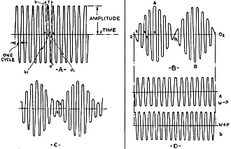
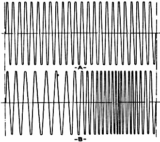
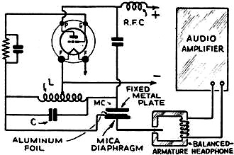
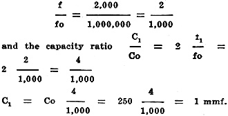
"Frequency Modulation" in Tomorrow's SetMajor Armstrong's new system of transmission which offers so many possibilities in the elimination of fading and static depends upon "frequency modulation"; explained here by the author. M. J. Cutter High-frequency currents generated by the oscillator of a modern radio transmitter have practically a pure sinusoidal form (sine wave), deviations from this form being corrected by adequate filtering systems. The pure sinusoidal current radiated from the antenna is commonly called the "carrier." The existence of the carrier can be detected by the receiver, generally through variations in the plate current. However, without the aid of high-frequency current from a local oscillator, the carrier cannot be transformed into an audible signal. As a figurative expression we might say that the "carrier" is similar to a blank sheet of paper - it is there but it does not carry a message. In order to perform this latter function the "carrier" must be modulated. By modulation we mean a continuous variation of the carrier from one set of conditions to another. The carrier, having a pure sinusoidal form, has 3 independent characteristics (like all pure alternating currents): (1) amplitude, (2) frequency and (3) phase. Any of these elements can be varied in accordance with the frequency or the amplitude of an audible current, and, therefore, we distinguish three forms of modulation, namely: (1) amplitude modulation, (2) frequency modulation, and (3) phase modulation. (It may also occur that the modulating current will cause continuous variations in more than one element; for instance, there may be simultaneously a variation of the amplitude and the frequency. The modulation then will be of the "mixed" type. However, we will limit this discussion to the simple forms in which only one factor varies. Amplitude Modulation All present-day broadcast stations use amplitude modulation, the action of which is described here. Figure 1A gives us an idea of a carrier before it is modulated. We see that the current during any cycle, the duration of which is T, starts with zero value (point a), increases gradually reaching a maximum value bb' at b' which corresponds to 1/4 of the period T. Then it decreases gradually until it reaches zero at T/2 (point c). After that the current becomes negative and at point d', or 3/4T, reaches a maximum value dd', which is equal to bb' but has an opposite direction. During the last quarter of the period T the current gradually decreases and becomes zero again (point e). The cycle is now completed. The value bb' (or dd') is the amplitude and remains the same for any cycle as long as the carrier is not modulated. Figures 1 Band C show two carriers of frequency for each modulated by an audio current of which the frequency f1, is considerably smaller than fo. On the time. axis, (Fig. 2B) ab represents the period of the carrier while the period of the modulating current is given by 00102. We see that during the period 00102 the amplitude of each R.F. cycle is no more a constant. It has a maximum value at A and B and becomes zero at 01. In this case we say that the R.F. current is completely modulated. On the other hand, the amplitude of the current shown in Fig. 1C never becomes zero, although it has a minimum value at a. Such a current can be considered as a combination comprising (a) a completely modulated current and (b) an unmodulated carrier. A mathematical analysis shows that a completely modulated carrier can be considered as consisting of two unmodulated waves. The frequency of one of these waves is equal to fo + f1, and the frequency of the other is fo -f1. The amplitude of both waves is equal to 1/2 the amplitude of the carrier. As an example, let us consider the case of a 1 megacycle carrier completely modulated by a 1,000 cycle audio frequency. Here fo = 1,000,000 and f1 = 1,000. The frequencies of the two waves are then 1,000,000 + 1,000 = 1,001,000 and 1,000,000 - 1,000 = 999,000. These two waves are commonly called "sidebands." When the R.F. carrier is modulated by more than one audio frequency the resulting current can be considered as the sum of elements of which everyone results from the modulation of the carrier by one of the audio-frequency currents. The number of sidebands will be twice the number of modulating frequencies. When the modulating current of the example just mentioned has a second and third harmonic the frequencies of which are respectively 2,000 and 3,000 cycles, the modulated current can be considered as consisting of 6 waves having the following frequencies: (1) 1,003,000; (2) 1,002,000; (3) 1,001,000; (4) 999,000; (5) 998,000, and (6) 997,000 cycles. In order to operate without distortion a radio receiver has to be capable of receiving simultaneously the six sidebands with the same efficiency - a condition which excludes sharp tuning. Together with the sidebands, a portion of the carrier is also transmitted when the latter is not completely modulated. It may seem at first glance that the unmodulated carrier is useless and that its suppression is desirable. A closer examination, however, shows that the two sidebands alone cause a beat, in the receiver, the frequency of which is twice the modulating frequency. In other words, such a modulation would lead to doubling the pitch of the transmitted sound (a condition which hardly conforms with good transmission!). The presence of the unmodulated carrier corrects this effect. Each of the sidebands "heterodynes" (produces a beat frequency) in the receiver with some portion of the carrier and the result is a beat note of the modulating frequency. Only a negligible portion of the two sidebands heterodynes together to produce an audio signal of double frequency. The above consideration explains why the modulation does not usually exceed some 35 per cent when high-quality broadcasting is desired. It is obvious that the carrier can be suppressed without affecting the quality of transmission if the receiver itself can supply the carrier from a local oscillator. Successful experiments have also been conducted on transmission while using a single side band and the carrier. Fig. 2 - Compare frequency modulation with amplitude modulation shown in Fig. 1. Fig. 3 - A simplified circuit for achieving frequency modulation; the practical method is much more complex. Frequency Modulation However, in frequency modulation (which is the basis of Major Armstrong's new system of transmission, described in the August 1935 issue of Radio-Craft, on page 75) the amplitude and the phase do not vary; the frequency is the only variable element. If the frequency of the unmodulated current is fo, the modulated frequency varies for a given amplitude of the audio signal between fo + f and fo - f; (f is the frequency variation). For instance, a frequency-modulated 1,000,000-cycle carrier for a given audio amplitude may have a variation f = 1,000 cycles, which means that while the audio signal varies during the cycle, the frequency of the carrier will vary between 1,001,000 cycles and 999,000 cycles. For a larger audio amplitude, the variation may be 2,000 cycles and the variation range therefore 1,002,000 and 998,000. If f1 is the maximum frequency variation which may be caused by the maximum audio amplitude, any instantaneous frequency value of the frequency-modulated carrier lies between fo + f1 and fo - f1. Frequency modulation is shown graphically at A and B in Fig. 2. It will be noted that the amplitude of the modulated wave (B) is the same as the carrier (A). There are several elements in an oscillator, the variation of which may cause a change in the frequency of the generated current. However, the most convenient method for producing a pure frequency modulation is to act either on the capacity or on the inductance of the oscillatory circuit - preferably on the capacity. Figure 3 shows a simple set-up for frequency modulation using capacity variation. In parallel to condenser C of the oscillatory circuit is connected a modulating condenser MC which is either a condenser microphone or a Baldwin headphone rebuilt for this purpose. The latter - is easily constructed as follows. The mica diaphragm is covered with thin aluminum foil, electrically connected to one end of C. A heavy, insulated metal plate is fixed in front of the diaphragm and is connected to the other end of C. The modulating frequency is supplied in this case by the audio amplifier. With such an arrangement a sound of a given frequency and amplitude will cause a sinusoidal variation of the part f. If the frequency variation f is small with comparison to fo, the ratio of the capacity change C1 to the total capacity Co is twice f. For instance, if Co = 250 mmf.; fo = 1,000,000, and we wish to have a maximum variation of 2,000 cycles; f is equal to 2,000. The ratio
Thus a variation of 1 mmf. in the capacity of the modulating condenser will produce a change of 2,000 cycles in the frequency of the generator. A mathematical analysis of frequency modulation, and carefully conducted experiments prove that a current modulated in the manner just described can be considered as consisting of an unmodulated carrier and an infinite number of sidebands. The sidebands are in pairs and their respective frequencies are: fo + p, fo -- p, fo + 2p, fo - 2p, fo + 3p, fo - 3p, etc. Where fo is the frequency of the carrier and p the modulating frequency. the amplitudes of the carrier and the sidebands depend upon a certain factor mf called the "modulation index." The modulation index mf is equal to a certain constant K multiplied by the ratio of the two frequencies mf = (K1fo.) / P We see that the amplitudes of carrier and sidebands depend upon the modulating frequency. While the amplitudes in each pair of sidebands in amplitude modulation are equal, the sidebands in frequency modulation generally differ. When the modulating index mf is small the amplitudes of the sidebands above the second are negligible and may be neglected. However, when mf increases, the importance of the higher sidebands becomes more noticeable. An "aperiodic" detector cannot produce an audio signal from a frequency-modulated current. The frequency-modulated signal must be converted into one which is amplitude-modulated in order to he made audible. This can be done by inserting a tuned circuit between the antenna and the detector, or by using filter systems. This means that practically any receiver with very sharp tuning can receive frequency modulated signals. The quality is another question; and in Armstrong's system, a special network of current limiting and filter circuits are used to maintain a high-quality output. Phase Modulation A mathematical analysis of phase modulation shows that similarly to frequency modulation the modulated current can be considered as consisting of an unmodulated carrier and an infinite number of pairs of sidebands. Using fo as the carrier frequency and p as the modulating frequency, the frequencies of the sidebands are: fo + p and fo - p; fo + 2p and fo -- 2p; fo + 3p, and fo - 3p, etc. The amplitudes of the carrier and the sidebands are a function of the modulating index mp (mp = K1fo) which unlike frequency modulation is independent of the modulating frequency. Here again when the modulating index is small, in other words when the maximum shift of the phase angle is small the bands above the second have practically no influence. An aperiodic detector cannot rectify a phase modulated wave (similar in this respect to frequency modulation). The transmitted wave has to be amplitude modulated before it reaches the detector. This is accomplished by inserting a tuned circuit between the antenna and the receiver or by using a filter system in the same position in the circuit. From the above consideration we may easily come to the conclusion that neither frequency nor phase modulation narrow the band width. As a matter of fact it appears that only under ideal conditions is the band width of the latter two systems equal to that in amplitude modulation, though it is true that in short waves the problem of band width is less acute than in the broadcast range. Very little can be said about the practical merits and defects of the latter two systems of modulation, as experimental data are quite limited.
Posted October 18, 2023 |
|

