Building Your Own Audio Frequency Choke Coils
|
||||||||||||||||||
One very satisfying aspect of 'rolling your own' audio frequency coils (aka chokes, aka inductors), is how well the simple inductance equations match measured end results. Unless you really manage to mangle the job, if you use the right equation and are reasonably careful to observe wire size, spacing (including insulation), and core diameter, you will be amazed at how close practice matches theory. Although strictly speaking audio frequencies run from a few Hertz up to maybe 15 kHz for people with really good hearing. My experience is that similar success can be had even into the low MHz realm with just a little tuning required. It's not until you get into the realm of self-resonance that everything starts falling apart with basic equations. Building Your Own A.F. Choke Coils By C. H. W. Nason
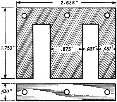
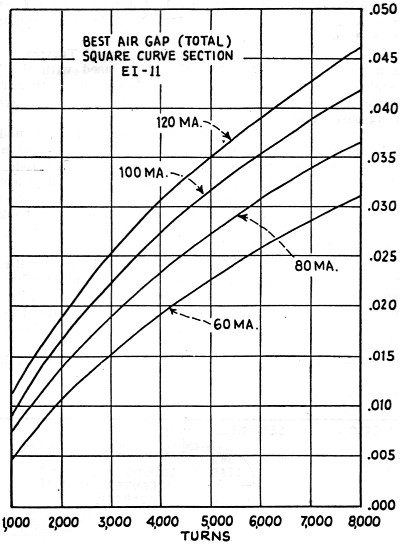
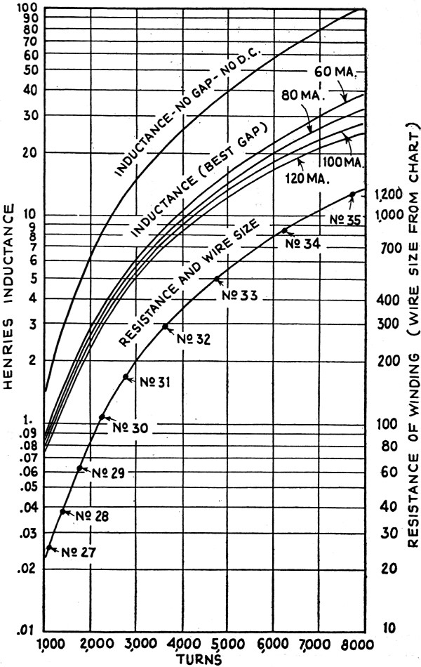
For a given inductance and D.C. through the core, the number and size wire may easily be determined by means of the chart above. For an inductance of 20 henries, with 120 ma. through the core, 6,700 turns of No. 35 wire should be used on the core indicated in Fig. 2. Filter chokes designed for a given inductance require calculations far outside the abilities of the average amateur. Before discussing actual simplified design methods it might be well, however, to discuss briefly the factors involved. Certain relations are involved in the design of the magnetic circuit which are briefly as follows:
In these equations: 1 = the magnetic path in cms. A = the cross section of the core in sq. cms. N =the number of turns. I = the current in amperes. pi = 3.1416 If we pass a gradually increasing current through the winding surrounding a magnetic material the relation of B to H is as shown in Fig. 1A. If the current through the winding is now decreased it will not follow the original path of the curve but will take another course as shown in Fig. 1B. Thus for a given value of H a twofold value of B corresponding to Q and to R in Fig. 1B are found. (This is due to the residual magnetism in the core and the condition is known as "hysteresis." Naturally, the smaller this loop the better is the core material for magnetic purposes.) If with a fixed D.C. magnetizing force a small A.C. voltage is superimposed, a minor hysteresis loop appears as is indicated in Fig. 1C. It is from the minor loop that we determine the permeability of the core material to alternating currents, and it is ua.c. that we employ in calculating the inductance of a transformer or choke. The factor ua.c. is defined as being equal to ΔB ΔH or the increment in B divided by the corresponding increment in H for a given A.C. flux. It may be readily seen that the value for ua.c. is something quite different from the arithmetical value for u obtained from the original B/H curve. This value is not really a constant as it varies over a range of A.C. flux densities. The relation of ua.c. to the A.C. flux is shown in Fig. 1D for two values of D.C. magnetizing force. These values are for a particular core material and are consequently not for design purposes. With ua.c. determined for a given D.C. flux density the inductance of the winding may he calculated from the equation. It will be noted in Fig. 1D that the value ua.c. increases slightly for the higher values of A.C. flux density but the increase has the effect of slightly adding to the inductance of the winding and is therefore beneficial in its effect except where sharply tuned circuits are involved. It an air-gap be provided in a magnetic core the D.C. flux density will fall off but an increase in the A.C. permeability will obtain. There is an optimum value for this relation which depends upon the characteristics of the particular iron chosen for the core material. That is to say: for some length of air-gap - for some substitution of a material having unit permeability for a portion of the magnetic path - the A.C. permeability will be at a maximum. Not only this, but the D.C. flux density may be varied over a wide range with but slight effect upon the inductance of the winding. In most A.F. transformers a certain percentage of air-gap is necessary (although it is provided in the case of the highest quality transformers only). The air-gap may be dispensed with only when the D.C. flux density is at zero through the use of parallel feed systems. In push-pull transformers the D.C. components are assumed to cancel but there are high values of A.C. in the core and a certain amount of D.C. is always present due to tube irregularities so that an air-gap is still essential to an economical design. In order to offer a series of chokes for the average experimenter to construct with a full knowledge of the characteristics that will obtain it is first necessary that a particular lamination be chosen which will be available to him. A core form which will offer a range in the neighborhood of 30 henries for all normal values of D.C. flux and which will at the same time lend itself to an economical design in so far as D.C. resistance is concerned may be achieved around the EI-11 lamination of the Lamination Stamping Company (located at Brackenridge, Pa.)
Window area, 0.575-sq.-in.; Volume, 4.03 cu. in.; Core weight, 1.13 lbs.; Area, 4.94 sq. cm. or .766-sq. in.; Length of path, 15.61 cm. or 6.13 in. Winding data from the charts is based on the use of enamel wire of the size indicated and with glassine paper between layers. The ends of windings should be straightened with pieces of fiber and the core itself should be protected with several layers of brown paper. In forming the windings a piece of wood should be cut to slightly less than the core dimensions and wrapped with one layer of string. After winding. this string may be pulled out and the coil removed from the wood form. The values for the air-gap given in the chart refer to the total gap and in the case of EI laminations the gap at the center and in each leg should be just half the value read from the chart. Any machinist will lend you a micrometer to assist in building up wafers of paper or of fiber to insert in the legs. The holes provided in the core offer ready means for mounting and for clamping in position by means of iron or brass straps in methods which will readily suggest themselves to the experimenter. Variations from the data in the charts may be achieved by varying the "stack" of the laminations. For double the stack (2 x 0.875-in.) the inductance will be doubled for a given current density and number of turns; while the resistance of the windings will be increased by but one-third. For one-half the stack specified, the inductance will be halved; and the resistance will be reduced by about 16 percent. We may thus achieve with this single type of lamination any value of inductance up to 60 henries with D.C.; or up to over 200 henries where no D.C. is employed. The core material employed in calculating the charts was Allegheny Super Dynamo Grade Steel Sheets and the calculations are based on the assumption that 1 volt of A.C. is superimposed on the D.C.; for high A.C. flux densities a slightly higher inductance will prevail. As an example, let us suppose that we desire a choke having an inductance of 20 henries at a current of 120 ma. on the core specified . Tracing through from the 20 henry line at the left edge of the curve we find that this cuts the 120 ma. line at 6,700 turns. We find from the wire size-resistance curve, that the wire size for this number of turns is No. 35 enamel; and that the resistance of the choke will be 1,100 ohms. Under these conditions the second chart shows that the air-gap is about 0.045-in. This means that 0.0225-in. of insulating material will be required in each leg of the choke core. Now, an efficient choke should not have a resistance so high as this unless designed for a specific purpose - for instance, let us suppose that a receiver employing a 2,500-ohm dynamic field in its filter system must be used with an external speaker and we desire to replace the original speaker field with a choke. In this case we would work backwards from the specifications that our choke must have a 2,500-ohm resistance. On the basis of economy, let us see what we can do with our choke design in order to reduce the resistance. As we noted before. increasing the height of the core stack by 100% increases the inductance of any form of winding by a like degree. On the basis of a square stack we start with an inductance of 10 henries at 120 ma. This calls for 5,000 turns of No. 33 wire, a total resistance of 450 ohms. Increasing the stack by 100% likewise increased the resistance by one-third. Our total resistance is therefore 600 ohms. Reference to the second chart indicates a total air-gap of 0.035 in. or .0175-in. in each leg.
Posted August 13, 2020 |
||||||||||||||||||