Wired Wireless |
|
As you might know, particularly if you are a frequent RF Cafe visitor, amateur radio operators (Hams) were prohibited from broadcasting during the entirety of World War II (see War Comes), ostensibly as a security measure. The concern was that people might unintentionally (or intentionally) convey information on troop positions and family names, domestic factory locations and activities, and the general state of the nation in regards to attitude and finance. Unlike today, that type of data was not easily gathered even by a dedicated deployment of internal spies. In the early 1940s, the majority of amateur radio activity was carried out in the form of Morse code, and operators were understandably concerned about losing proficiency due to lack of use. In order to mitigate the opportunity for 'fist' atrophy, many Hams set up 'wired wireless' stations between residences and club meeting locations. This particular system was designed to couple to the local overhead electric power lines, but there were also private setups with dedicated lines between locations. Then, as now, one of the biggest hurdles with conducting power-line carrier communications is coupling through transformers, which do not efficiently operate at frequencies of more than a few kHz. Wired Wireless Low-Frequency Communication Over Commercial Power Lines By Byron Goodman,* W1JPE If you have the urge to warm up the old bug and. chew the rag with your fellow hams, here is one way to do it without too much trouble. The distance that can be covered is usually limited to a few miles (unless some enterprising experimenter cooks up an improvement), but that's a lot better than nothing. Here's how to get started.
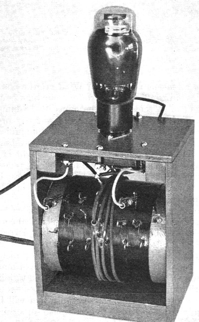
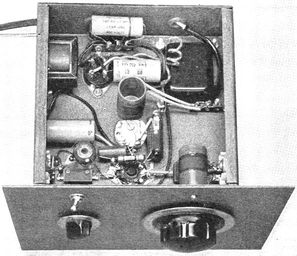
A 25-watt transmitter for wired wireless. Since variable condensers large enough to give much frequency change are out of the question, a tapped coil is used for tuning.
A back view of the transmitter shows the antenna condensers, C5, C6 and C7, and the clip used to select the proper combination for correct loading. Note also the 4-turn coupling loop around the tank inductance. As pointed elsewhere in this issue, the curtailment of normal amateur radio communication need not throw all amateur communication into a state of suspended animation. For example, it is a well-known fact that so-called "carrier current" communication is used by both telephone and power companies for long-range work over their wires, and the thought that the 110-volt power lines might be utilized for amateur communication has no doubt occurred to many hams during the past several months. Let's look at the picture a little more closely. Low-frequency radio waves do not radiate as easily as high-frequency ones because the radiation efficiency increases with the frequency. While it is true that they can be radiated, it is equally true that the radiators become large affairs, and any small antenna for such work is practically hopeless. This is a headache to the long-wave radio engineers but a boon to the telephone and power company men - and possibly to the amateur. By keeping the frequency low, the radio energy can be made to travel along wires with little or no radiation, depending mainly upon the balance of the two wires and their spacing. The r.f. follows along the line in much the same manner as the 60-cycle current except that it is much more susceptible to the by-passing effects of lines that connect to the main line. This is one factor that limits the range of 110-volt power-line communication because, while the power and telephone companies can put chokes in strategic points along the lines that are carrying carrier currents, the amateur must be content with the line as he finds it. Another factor involved in the amateur use of low-frequency carrier current communication is the proper choice of frequency and power. The amateur might use a frequency around 40 or 50 kc. without any danger of radiation and consequent interference to radio services, but there would be the possibility of interference with established telephone and power company service, with its resultant ill will and possible legislation. The same holds true of frequencies up to about 160 kc., the upper limit of the frequencies used by the services mentioned. From 160 to 200 kc. there seem to be no "wired wireless" services, but the chances for radiation increase and there is the possibility of broadcast receiver interference in receivers using a 175-kc. i.f. By keeping the power down to a low value (less than 50 watts), there isn't much chance for any appreciable radiation and radio interference. In any event, the radiation can be checked roughly by listening at a distance on a long-wave receiver. There still remains the possibility of harmonic interference with local b.c. receivers, but a judicious selection of frequency which keeps the harmonics farther than 10 kc. away from the local b.c. stations will practically eliminate this problem. The use of frequencies higher than 200 kc. is unwise because of the increased chances for radiation. We once had the idea of using the regular 80-meter transmitter on the power lines for local work without QRM, and tested it with a receiver about three miles away that was also coupled into the 110-volt line. The signal came in over the power lines all right - it was a fairly strong one, at that - but the signal that came in through the regular receiving antenna was not more than three S points weaker and represented a signal that would certainly be considered a violation of the law under the present FCC Order No. 87-A. Hence utilization of our amateur transmitters without modification is not a possibility, convenient as it would be. So, rather than skate on thin ice, we propose that amateur wired wireless be conducted on frequencies between 160 and 200 kc., with powers not exceeding 50 watts. The frequencies should be selected with proper consideration of possible harmonic interference in the b.c. range and with the 175-kc. i.f. amplifiers that may be in some local receivers. After we find out what can be done in various localities and under a wide variety of circumstances, it may be possible for us to spread the limits a bit, but we should consider at all times the possibility of interference with other services and act to avoid it. This is not a brand-new thing, but something that has been tried before and made to work by other amateurs. Mr. John E. Williams, W2BFD, has put a 175-kc. signal over the lines for distances up to five miles1 without any detectable interference to other services, and with the equipment to be described in this article we got a good signal over a distance of two miles. There are so many possibilities for complicated routing (and by-passing!) that it is impossible to predict the range of any installation within 200%, and it makes a nice thing for amateurs to try for themselves. It might be expected that greater distances could be covered in rural areas than in thickly populated centers, but that remains to be seen. That is the attraction to wired wireless - like high-frequency DX its range is fairly unpredictable. A Wired-Wireless Transmitter Any problems connected with the design and construction of an oscillator for the 160-200-kc. range center around the tank circuit. Using an L-C ratio that will give a decent order of stability means using a tank capacity of at least 0.002 μfd., and the average ham no longer has variable condensers of that size kicking around the shack. A number of b.c. tuning condensers can be connected in parallel to get the necessary capacity, but we finally decided upon the use of mica condensers, and a check on their performance showed them to be entirely satisfactory for the work. Using mica condensers means changing frequency by changing the inductance unless a large variable shunting condenser (500 μμfd. or more) is available. Tapping the coil is simpler than trying to build a variometer to cover the range, and we ended up with a transmitter that is fairly simple (and reminiscent of 12 or more years ago!). It is not exactly a thing of beauty, but the fact that it doesn't cost very much to put together should compensate for its artistic shortcomings.
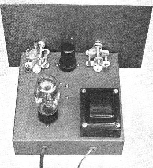
A top view of the converter. Note the adjusting screw of the output tank condenser, C5, just in front of the 6SA7.
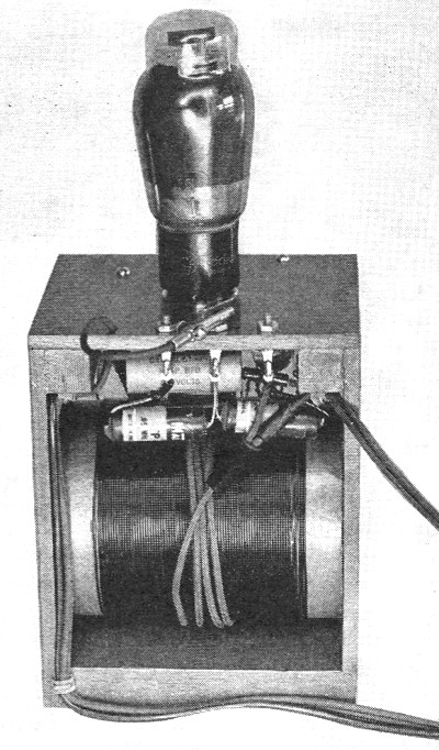
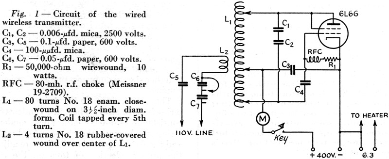
A bottom view of the converter also gives an idea of the panel layout. The output tank coil, L3, can be seen in the center of the chassis; L2 is directly under the oscillator tuning dial, and the mixer grid coil, L1, can be seen at the right, next to the toggle switch. Padding condensers C4 and C2 are mounted on the left- and right-hand sides of the chassis, under their respective tuning condensers. The circuit, shown in Fig. 1, is the conventional series-feed Hartley. The tank condenser, C1-C2, consists of two 0.006-μfd. mica condensers in series (to decrease the chances for breakdown), and the frequency and excitation are adjusted by the proper selection of taps on the coil. The "antenna" coupling is adjusted by the proper selection of condensers in series with the coupling coil, L2. About the best source of cardboard tubing for the inductance is our old friend of early broadcast-receiver days, the Quaker Oats box. A look at the local grocery showed this to be the only cheap source of 3 1/2-inch diameter cardboard tubing, and if the kitchen won't furnish you with one, buying a box in the store won't ruin your financial standing. After the contents have been removed and the box cut down to a length of about 4 3/4 inches, the box should be given a coat or two of shellac. We finished ours off with gray lacquer, but this isn't necessary for the proper operation of the transmitter. The 80 turns of No. 18 enameled wire should be wound on as tightly as possible. The taps at every 5th turn are made by twisting a 1-inch loop of wire tightly for several turns at each tap so that it will not twist apart as the rest of the coil is wound. When the coil is finished, the loops can be scraped bare of insulation with a knife or fine sandpaper. As a final touch, spots of Duco cement can be used to secure the twisted portions. The framework used to support the coil and other components was made of 1/4-inch plywood except for two corner strips at the top of 1/2-inch square stock and the two bottom strips of 1- by 2-inch wood. The whole assembly is held together by brads and glue. The box was made just wide enough to allow the coil to be pushed in, and the spring of the sides is enough to hold the coil firmly in place. Our box measures 6 7/8 inches high by 5 1/4 inches long by 4 1/4 inches deep. The tube socket is set down in a hole in the center of the top of the framework. The tank condensers, C1 and C2, are fastened underneath by screws. The grid choke, RFC, is supported on a 1/2-inch pillar on the rear screw which holds the socket. The coupling condensers, C5, C6 and C7, are supported on lugs under the heads of the screws used for coupling taps at the rear of the box. The flexible leads to the coil are fastened to the terminals of the tank condensers. When the transmitter is completed, it can be hooked up to a power supply giving 350 or 400 volts at 100 ma. A meter and key should be put in the positive lead, as shown in Fig. 1. Some may object to the key in the positive lead, but it is convenient to have it there because as long as one's hand is off the key there is no chance for shock when adjusting the coil taps. A certain amount of care must be exercised, of course, and we heartily recommend that all tuning adjustments be made with one hand in your pocket. The first tuning should be done without the oscillator coupled to the line. Set the clips so that there are 60 turns between grid and plate and attach the cathode tap 25 turns from the grid end. Press the key and read the plate current, and then try again with the cathode tap on either side of this position. The setting of the cathode tap which gives the lowest plate current reading is the one to use. With a 350-volt supply, the no-load plate current should run around 25 or 30 ma. Connect the output into the line and set the coupling clip so that it isn't shorting any condenser (loosest coupling). The plate current will increase to 30 or 40 ma., depending upon the frequency of the transmitter, and the note can be checked by listening to a harmonic with your communications receiver set to the lowest frequency range. The coupling can be increased until the note becomes too rough or yoopy, which indicates that the coupling is too tight or that the cathode tap needs adjusting. The same rules hold for adjusting a transmitter on 170 kc. as on the higher frequencies, and a little experimenting will bring back the old touch. With no loading at all, the signal from these low-frequency oscillators is truly beautiful - they should be coupled up to the point where the note starts to go sour, and that is the place to stop. The note will roughen up before it chirps - you can tolerate the roughness, but the chirp makes it difficult to copy. And be careful in making adjustments - you have deliberately hooked into the 110-volt line, and you can get a good shock from it! The Wired- Wireless Receiver
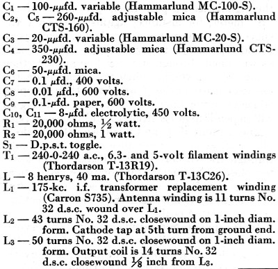
Fig. 1 - Circuit of the wired wireless transmitter. The first thought in building a receiver for the wired-wireless frequency range might be to throw together the old reliable" detector and one step," but this has several disadvantages that make its construction unwise. In the first place, the frequency is likely to be pulled around a bit by someone turning on a light in another room, thus necessitating some retuning. Further, regenerative detectors at these low frequencies are likely to be too selective and, since one must tune off-frequency slightly with a regenerative detector to obtain the proper beat note, it is not possible to realize full signal strength except with rather low beat notes. On the other hand, a converter for the 175-200 kc. range that will feed into a communications receiver costs no more than the regenerative receiver, and it has the advantage that any noise-limiting devices on the communications receiver can be utilized. The noise at these frequencies that comes in on the 110-volt line is rather high, particularly in localities where there are a number of oil-burning furnaces (with electrical ignition) and similar sources of electrical noise. The converter to be described is a simple affair, and it can be used to copy long-wave stations for code practice and general snooping as well as for the reception, of amateur" wired-wireless" signals. The circuit of the converter is quite conventional (Fig. 2). It consists of a 6SA7 mixer tube with the output on 1950 kc., so that it can be hooked into any communications receiver which will tune to 1950 kc. The grid circuit tunes the range 150 to 200 kc. and, in order to give the out-put frequency of 1950 kc., the oscillator tunes from 1800 to 1750 kc. The oscillator could also be made to tune from 2100 to 2150 kc., but by using the former range it can be checked on a communications receiver which only covers the amateur bands.
Fig. 2 - Wiring diagram of the low-frequency converter. The converter is built on a 7- by 7- by 2-inch chassis, and only a few points need be mentioned because the arrangement of parts can be seen in the photographs. The tuning condensers are bolted to the chassis in a position that will allow the panel to be supported by the panel bearings of the condensers. The toggle switch and the screw holding the oscillator coil also hold the panel to the chassis. The mixer and oscillator padding condensers, C2 and C4, are fastened to the sides of the chassis under their respective tuning condensers, and C5, the output circuit tuning condenser, is mounted on the chassis directly behind the 6SA7. The output coil, L3, is fastened to the chassis near its tuning condenser. Both L2 and L3 are wound on l-inch bakelite forms (Millen 4500). L1 is a winding from a 175-kc. transformer. The particular one we used came wound on a piece of dowel which could have been used to mount it except that we used up the dowel in another experiment, so the winding was slipped over a polystyrene stand-off insulator (Millen 30001) which was cemented to the chassis. However, the dowel will serve just as well. The primary winding for L1 is put on after two layers of cellophane scotch tape have been wound over L1 to serve as insulation. The primary can then be wound on and cemented with coil dope or Duco cement. The converter is put into service by connecting its output to your communications receiver and plugging in the line cord of the converter. While both the converter and receiver are warming up, set the receiver to 1950 kc. Then adjust the output trimmer C6 for maximum noise from the receiver. Next the converter oscillator range can be checked by setting the oscillator tuning condenser, C3, to minimum capacity and the receiver to 1800 kc. It should then be possible to tune in the converter oscillator signal by adjusting C4 until the signal is heard. Check the range of the oscillator by setting C3 at maximum - if it can be tuned in at 1750 kc. on the receiver your range is right on the nose. If the range is too great (oscillator is lower than 1750 kc. at maximum capacity) it indicates that fewer turns are required on L2, and vice versa. It is not critical, of course, since the converter is not ganged. The receiver can now be reset to 1950 kc. and C1 and C3 set to the middle of their ranges. Then adjust C2 for maximum noise (with S1 closed) and the converter is lined up for action. It will be found that the mixer tuning control is not too sharp and will only need attention after the signal has been tuned in with the main tuning control, C3. Remember that C3 tunes backward to the usual way - it is tuning the converter to 150 kc. when it is at minimum capacity and to 200 kc. when it is at maximum capacity, the reverse of the mixer condenser action. The coupling switch, S1, is included so that the converter will not be pumped full of r.f. during transmission periods, and it should be used to disconnect the converter from the line whenever the transmitter is being keyed. General Any group of hams within several miles of each other in a city and up to ten or more in the country will find they can have plenty of fun and operating practice with wired wireless. We suggest that they keep to around 165 kc., to reduce the chances for radiation, and that the power be kept low - one or two 6L6s will give plenty of output. On several occasions we noticed a difference in signal strength, very probably caused by different routing or loading of the line, and it may work out in some instances that 24-hour communication is impossible or unreliable. Above all, however, remember to keep away from other services and from interfering with broadcast receivers - continued wired-wireless operation will depend upon our staying in our own backyards and not getting in anybody's hair. * Assistant Technical Editor, QST. 1 Williams, "Wired Wireless for Remote Control," QST, February, 1940.
Posted June 11, 2020 |
|