The "Twin-Lamp" Standing Wave Indicator |
|
Even if you have no use for building a "twin lamp" standing wave indicator for a twin lead transmission line (solid or open ladder type), this article makes an interesting read for its theoretical description of how the device works based on current phases in the circuit. A pair of flashlight bulbs and couple feet of wire is all that is needed. When operating properly, the "twin lamp" indicator indicates by virtue of whether one or both bulbs are illuminated whether there is a significant standing wave present on the line. Author Charles Wright warns that the VSWR level cannot be reliably determined based on relative brightnesses of the two bulbs; it is meant for use as a best case indication for tuning and/or as a gross fault indicator. With a little ingenuity, you could build a twin lamp standing wave indicator for use with coaxial cable if you enclosed the coupling section in a metal enclosure. LEDs could probably be substituted for the incandescent bulbs. The "Twin-Lamp" Standing Wave Indicator The Poor Man's Standing-Wave Indicator By Charles Wright, W4HVV One of the most popular indicating devices ever to grace a ham shack is the old familiar loop and flashlight bulb. Rather than relegate it to the junk box, W4HVV has made a twin out of it, and thus gives us a clever tool to cope with our new-found standing-wave consciousness. And don't pass it up just because it looks so simple!
The "Twin-Lamp" standing-wave indicator consists of two small flashlight bulbs and an extra length of 300-ohm line, but it is the most convenient gadget imaginable for checking standing waves on a length of 300·ohm Twin-Lead. When it was found that none of the standing-wave meters so far described in amateur publications1,2 would operate satisfactorily on my 300-ohm lines at 50 and 144 Mc., it was decided to search elsewhere for ideas for something that would do the job. Only two informative articles were found in the literature on directional couplers, and both dealt primarily with instruments for use in wave guides. The problem was then one of simplification and adaptation for use with two-wire lines. The first article3 described directional couplers made entirely of distributed constants which, in effect, sampled the line current at quarter-wave intervals. After several weeks of experimenting with various lengths of 72-ohm line (the XYL called them "snakes "), light bulbs and various other gadgets, this idea was given up. The indicators were good only for one frequency, and were so massive that when they were attached to the line they caused more standing waves than were present to begin with. The second,4 though it seemed completely irrelevant at first, held the real answer to my problem. The indicator to be described was evolved by considering the electrostatic and electromagnetic components of the traveling wave in a wave guide analogous to the voltage and current rela-tions in a two-wire line. The Theory
Fig. 1 - A simple representation of the operation of the "Twin-Lamp" standing-wave indicator. The sketch at A shows the current inductively-coupled in the loop, for a wave traveling from left to right, and B shows the current that is capacitively-coupled into the loop. C shows how the currents combine to light lamp A and not lamp B. Referring to Fig. 1-A, a current, IL, in the line would induce a current, I1, in a loop near the line, as shown. If the reactance of the loop is small compared to the resistance of the bulbs A and B, the current I1 will lag IL by 90°. This current will, of course, be the same through lamps A and B, and will cause them to burn with equal brightness if they are identical. Now from Fig. 1-B, we see that bulbs A and B are across the line and in series with a small capacity C. This capacity is, of course, the distributed capacity between the loop and the line. If the reactance of this capacity is large compared to that of A and B the current I2 will flow and will lead the voltage across the line by 90°. If A and B are identical the current will divide equally between them. Since I1 lags IL. by 90° and I2 leads EL by 90°, it is apparent that if IL and EL are in phase with each other, I1 and I2 will be exactly out of phase. Fig. 1-C is a combination of the circuits explained above. Condenser C is the capacity between the wires of the loop and the line. Currents I1 and I2 are shown as they appear in Figs. 1-A and 1-B. It is now evident that bulb A will light from the sum of I1 and I2 and bulb B will light from the difference between these two currents. This is the case for a wave traveling toward the right. In the case of a wave traveling toward the left, the currents will add in bulb B and tend to cancel in bulb A. Thus the device is a form of "directional coupler." When the line is terminated on the right-hand side (marked "load" in Fig. 2-C) by a resistance equal to the characteristic impedance of the line, there is no reflected wave and only bulb A will light. If the load is something different, there will be some reflected energy, and lamp B will burn along with A, the relative brilliance depending upon the relative magnitudes of the transmitted and reflected energy. These facts are what make the device so useful as a standing-wave indicator. In the foregoing discussion, three conditions were set up: bulbs A and B should be identical; the reactance of the loop should be small compared to the impedance of A and B; and the reactance of the coupling capacity should be high compared to the bulb impedance. To satisfy the first, bulbs of the same characteristics were used, and in the interests of sensitivity, these were 2-volt 60-ma. flashlight bulbs. For the second and third considerations, the length of the coupling loop must be kept short compared to a wavelength. It was found that, for 50-Mc. operation and a transferred power of about 20 watts, a loop length of about 4 inches was a good compromise between sensitivity and the satisfaction of the above conditions. For 28 Mc. it can run a few inches longer, and at 144 Mc. an inch or so shorter. In any event, the length is not critical. Building a "Twin-Lamp"
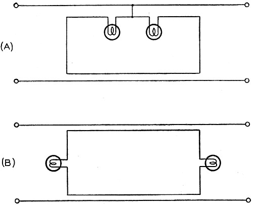
Fig. 2 - Two practical circuits of the "Twin-Lamp" for use with 300-ohm line. The circuit at A is more sensitive and is the one illustrated in the photograph. The construction of a "Twin-Lamp" indicator is about the easiest thing you'll run into in amateur radio. Two possible circuits are shown in Fig. 2. The circuit of Fig. 2-A is more sensitive than that of 2-B, but it requires opening the line to connect it into the circuit. The circuit of Fig. 2-B is convenient to use in initial work, but the final touching-up at my shack is always done with the more sensitive indicator of Fig. 2-A. The photograph shows how simple the gadget of Fig. 2-A is to build - the construction of the Fig. 2-B type will then be obvious. A short length of Amphenol 300-ohm Twin-Lead that is to be used as a test section has its insulation removed from one wire for a distance of about 1/4 inch, just enough to permit soldering a lead to the wire. Another piece of Twin-Lead, from 4 to 10 inches long (depending on the frequency and the power level), is short-circuited at each end. One wire is cut, in the exact center of this loop, and the wire peeled back on either side just far enough to provide leads to the flashlight bulbs. The short lead from one side of the test section is then soldered to the tips of the flashlight bulbs, and the leads from the loop are soldered to the threaded sides of the flashlight bulbs. A few pieces of tape can then be wrapped around the test section and the coupling loop, to hold them together. If one has several hundred watts of power available, the coupling loop can be made small, on the order of 4 or 5 inches for 28 Mc. This is preferable to using a larger loop with larger flashlight bulbs. In any event, it is highly advisable to be careful when first applying power, since the lamps can burn out fast. Adjustable coupling at the transmitter, or other means for controlling the r.f. power in the line, will avoid any burn-out difficulties. To assure yourself that the indicator works as stated, connect the test section to your transmitter output coupling in place of your regular 300-ohm line. Hang a 300-ohm noninductive resistor across the other end of the test section and apply power. As you increase the power, the lamp toward the transmitter will start to burn, but the other one should remain dark. The coupling can be increased until the one lamp shows full brilliancy without the other one showing any color, if the resistor is nonreactive. Reduce the power from the transmitter and short the resistor, and both lamps will light. This indicates a high order of standing-wave ratio. If the resistor is removed and the test-section end left open, it will probably be difficult to get any indication in the lamps, indicating that the sensitivity of the device depends to some extent upon its position in the line, for high values of standing-wave ratio. Comparison tests show that with the lamp on the transmitter side burning at almost full brilliancy, the other lamp will start to show color when the s.w.r. exceeds about 1.5. You can check this by substituting other values of resistance for the 300-ohm termination, remembering that the s.w.r. will be the ratio of the terminating resistance to 300 (if the termination is greater than 300 ohms) or the ratio of 300 to the termination (if the termination is less than 300 ohms). For example, either a 450- or a 200-ohm termination will give a 1.5 s.w.r. Since a ratio of 1.5 or less is good in amateur practice, if the lamp toward the transmitter shows full brilliancy when the other shows nothing, you know your feedline is up among the elite! It should be pointed out that this is only a standing-wave indicator, and the relative brilliance of the bulbs does not necessarily indicate the actual ratio on the line. In fact, it has not yet been proven that there is not some load condition other than ZL = Z0 that will cause the load-side bulb to extinguish. Unfortunately, a rigid mathematical proof of the device is not as simple as its mechanical construction, and the validity of the device under all possible conditions is still being checked. However, the gadget is so simple that it was thought best to describe it at the present time. Its convenience lies in its simple construction and the fact that, with two lamps, one always has a check on the power level in the line as well as a standing-wave indication. To use the indicator while adjusting an antenna match, connect it in the line within sight of the matching device. Make your adjustments until the bulb away from the transmitter is completely extinguished, with the other one burning. If your adjustments reflect a large change in impedance at the transmitter, the coupling may change, but this will be indicated by the brilliancy of the lamp on the transmitter side. For a cross-check, the indicator can be connected in the line near the transmitter, and the relative brightness should be the same as it was in the position near the antenna, provided your line doesn't pick up some impedance "bumps" or unbalance to ground by being run too close to metallic objects. If the indicator bulb burns only on the transmitter side, it shows that you're in business with more r.f. in the antenna than you've had in a long time! Acknowledgment I wish to express my gratitude to R. R. Brown, professor of electrical engineering, North Carolina State College, for his help in deriving an explanation for the indicator, and to the technical staff of the ARRL for aid in testing the device. 1 Jones, M. C., and Sontheimer, Carl, "The Micromatch," QST, April, 1947. 2 Patterson, H. O., Morris R. M., and Smith, J. W., "A Standing-Wave Meter for Coaxial Lines," QST, July, 1947. 3 Mumford. W. W., "Directional Couplers," IRE Proceedings, Feb., 1947. 4 Early, H. C., "A Wide-Band Directional Coupler for Wave Guide," IRE Proceedings, Nov., 1946.
Posted December 13, 2019 |
|