Practical Applications of Simple Math - Part II
|
|
Recognizing that many people were reluctant to approach the theoretical aspect of electronics as it applied to circuit design and analysis, QST (the American Radio Relay League's monthly publication) included equations and explanations in many of their project building articles. Occasionally, an article would be published that dealt specifically with how to use simple mathematics. In this case, the June 1944 edition, we have the second installation of at least a four-part tutorial that covers resistance and reactance, amplifier biasing (tubes since the Shockley-Bardeen-Brattain trio hadn't invented the transistor yet) oscillators, feedback circuits, etc. I do not have Part I from the May 1944 edition or Part IV from the August 1944 edition, but if you want to send me those editions, I'll be glad to scan and post them (see Part III here). Practical Applications of Simple Math: Part II - Plate and Screen Voltages By Edward M. Noll, EX-W3FQJ Whenever the d.c. plate current flows through any resistance placed in the plate circuit of a vacuum tube as a load or coupling medium, it is obvious that the voltage at the plate will be less than the supply voltage because of the voltage drop across the resistance.
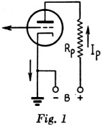
In Fig. 1 the plate voltage is Ep = Eb - RpIp.
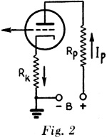
Example: In Fig. 1, Eb = 250 volts. Rp = 10,000 ohms. Ip = 10 ma. (0.01 amp.). What is the plate voltage, Ep? Ep = 250 - (10,000) (0.01) = 250 - 100 = 150 volts. Since true plate voltage is the voltage between plate and cathode, the voltage drop across the cathode resistor, Rk in Fig. 2, as well as the drop across the plate resistor, Rp, must be subtracted from the supply voltage in calculating plate voltage.
Ep = Eb - IpRp- IpRk. = Eb - Ip(Rp + Rk).
Example: In Fig. 2, Eb = 250 volts. Rp = 25,000 ohms. Rk = 2000 ohms. Ip = 5 ma. (0.005 amp.). What is the plate voltage, Ep? Ep = 250 - (0. 005) (25,000 + 2000) = 250 - (0.005) (27,000) = 250 - 135 = 115 volts.
One advantage of transformer coupling between audio-amplifier stages is that the inductance of the transformer primary winding will provide a high-impedance load for the tube at audio frequencies, while the d.c. resistance of the winding is sufficiently low to cause only a small drop in d.c. plate voltage.
Ep = Eb - IpRt
Example: In Fig. 3, Ep = 250 volts. Ip = 20 ma. (0.02 amp.) Rt = 100 ohms. What is the plate voltage, Ep? Ep = 250 - (0.02) (100) = 250 - 2 = 248 volts.
Screen voltage is determined in the same manner as plate voltage, using the screen current to calculate the voltage drop across the screen resistor. Ep = Eb - IpRp Es = Eb - IsRs
Eb = 250 volts. Ip = 5 ma. (0.005 amp.). Rp = 20,000 ohms. Is = 2 ma. (0.002 amp.). Rs = 75,000 ohms. What are the plate voltage, Ep, and screen voltage, Es? Ep = 250 - (0.005) (20,000) = 250 - 100 = 150 volts. Es = 250 - (0.002) (75,000) = 250 - 150 = 100 volts.
In the circuit of Fig. 5, both plate and screen currents flow through the common resistor, R1, so that plate and screen currents must be added in calculating the voltage drop across R1. Ep = Eb - (Ip + Is) (R1) - IpRp Es = Eb -" (Ip + Is) (R1) - IsRs.
Eb = 250 volts. Rp = 40,000 ohms. Rs = 200,000 ohms. Ip = 2 ma, (0.002 amp.) Is = 0.5ma. (0.0005 amp.). R1 = 20,000 ohms.
What are the plate voltage, Ep, and screen voltage, Es? Ep = 250 - (0.002 + 0.0005) (20,000) - (0.002) (40,000) = 250 - 50 - 80 = 120 volts. Es= 250 - 50- (0. 0005) (200,000) = 250 - 50 - 100 = 100 volts.
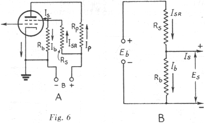
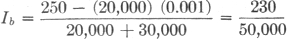
Es = RbIb.
Example: In Fig. 6-B, Eb = 250. Is = 1 ma. Rs = 10,000 ohms. Rb = 40,000 ohms.
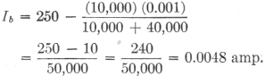
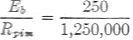
What is the screen voltage, Es? Es = IbRb. Since Eb is equal to the sum of the voltages across Rs and Rb, Eb = RsIsr + RbIb. Also, since both Ib and Is must flow through Rs, Isr = Ib + Is. Substituting this value for Isr in the above equation, Eb = Rs (Ib + Is) + RbIb. Transposing, RsIb + RbIb = Eb - RsIs Ib(Rs + Rb) = Eb - RsIs
Substituting known values,
Then, Es = (0.0048) (40,000) = 192 volts.
Eg = IgR2
Substituting, Screen and plate voltages are calculated as before.
Example: In Fig. 7, Eb = 250 volts. Ec = 100 volts. R1 = 49,000 ohms. R2 = 1000 ohms. R3 = 30,000 ohms. R4 = 20,000 ohms. R5 = 20,000 ohms. Is = 1 ma. (0.001 amp.). Ip = 5 ma. (0.005 amp.).
What are the grid-biasing, screen and plate voltages? Eg = = 2 volts (negative in respect to cathode). Ep = 250 - (0.005) (20,000) = 250 - 100 = 1.50 volts. Es = IbR3
= 0.0046 amp. Es = (0.0046) (30,000) = 138 volts.
With the meter disconnected, the plate voltage will be Ep = Eb - RpIp. However, with the meter connected, the current, Im, will flow through Rp. Thus, the voltage drop across Rp will increase and the plate voltage will be lowered, especially when the resistance of the meter is low in comparison with Rp. The equivalent circuit with the meter connected is shown in Fig. 8-B, in which Rpi is the internal resistance of the tube which is assumed to be constant with a change in plate voltage. The new plate voltage desired is the voltage across Rpi (or Rm) which is Ep = Eb - (Ipm) (Rp), where Ipm is the new current when Rm is connected. In other words, Ep is the difference between the terminal voltage and the voltage drop across Rp.
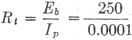
Example: In Fig. 8, Eb = 250 volts. Ipi =0.1 ma. (0.0001 amp.) Rp = 1 megohm (1,000,000 ohms) Rm = 1000 ohms per volt (300-volt scale). What is the true plate voltage with the meter disconnected and what voltage will be measured by the meter when it is connected? Ep = 250 - (1,000,000) (0.0001) = 250 - 100 = 1.50 volts = plate voltage without meter connected. As stated above, when the meter is connected, Ep - Eb - (Ipm) (Rp). Since Ipm is not known, its value must be found before the equation can be solved. To find Ipm, the resultant resistance of Rm and Rpi in parallel must be found, and this, in turn, requires that Rpi be determined. This can be done by considering the circuit before the meter is connected. The total circuit resistance, Rt is then given by
= 2.5 megohms.
Also, Rt = Rp + Rpi Rpi = Rt - Rp = 2,500,000 - 1,000,000 Rpi = 1,500,000 ohms = 1.5 megohms. The resistance of the meter, Rm, is given as 1000 ohms per volt. Since the meter has a 300-volt scale, its resistance is 300,000 ohms, or 0.3 megohm. Rpim, the resultant resistance of Rpi and Rm in parallel is given by Rpim = This gives the total circuit resistance in Fig. 8-B as Rt = Rp + Rpim = 1 + 0.25 + 1.25 megohms. The new current, Ipm, is then Ipm = Then Ep = Eb - (Ipm) (Rp) = 250 - (0.0002) (1,000,000) = 250 - 200 = 50 volts = voltage indicated by meter reading.
When the tube is conducting, Ep = Eb - IpRp ;= 250- (0.015) (10,000) = 250 - 150 = 100 volts. When the tube is not conducting, there is no voltage drop across Rp and the plate voltage is 250, the same as the supply voltage, Eb.
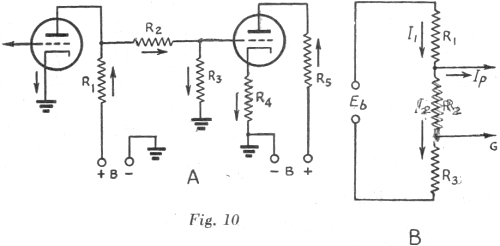
Example: In Fig. 10, Eb = 250 volts. Ip = 5 ma. (0.005 amp.) R1 = 10,000 ohms. R2 = 75,000 ohms R3 = 25,000 ohms. What are the plate voltage of the first tube, and the grid voltage of the second tube? The total drop across all resistors is, of course, equal to the applied voltage, Eb. The voltage, across R1 is R1I1, while that across R2 and R3 in series is (R2 + R3) (I2), bearing in mind that no current is being drawn from the tap, marked G in Fig. 10-B, so that the same current flows through. R2 and R3. Then, Eb = R1I1+ (R2 + R3) (I2) Since both Ip and I2 flow through R1, I1 = Ip + I2 Substituting this value for I1 in the preceding equation, Eb = (Ip + I2) (R1) + (R2 + R3) (I2). Substituting known values, 250 = (0.005 + I2) (10,000) + (75,000 + 25,000) (I2) = 10,000I2 + 50 + 100,000I2 110,000I2 = 200 I2= 0.0018 amp. = 1.8 ma. The plate voltage of the first tube is equal to the sum of the voltage drops across R2 and R3. Ep = I2 (R2 + R3) = (0.0018) (100,000) = 180 volts. The grid voltage of the second tube is equal, to the voltage drop across R3. Eg = I2R3= (0.0018) (25,000) = 45 volts.
Posted June 5, 2023 |
|

 In Fig. 2 the plate voltage is
 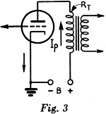 In Fig. 3 the only resistance affecting
the plate voltage is that of the transformer primary winding, Rt, so
In Fig. 3 the only resistance affecting
the plate voltage is that of the transformer primary winding, Rt, so
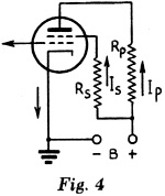 Example: In Fig. 4,
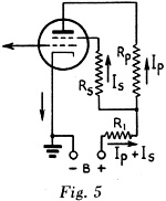 Example: In Fig. 5,
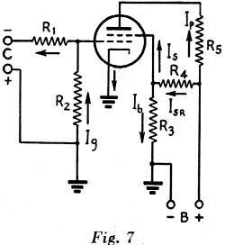 In the circuit of Fig. 7, both screen and
grid-biasing voltages are taken from voltage dividers. In the case of the divider
in the grid circuit, the voltage division is in exact proportion to the resistance
values of the divider sections, since it is assumed that the grid is biased so that
no grid current flows. Therefore, the grid-biasing voltage, Eg, is the
voltage developed across R2 by virtue of the current flowing through
it from the bias supply.
In the circuit of Fig. 7, both screen and
grid-biasing voltages are taken from voltage dividers. In the case of the divider
in the grid circuit, the voltage division is in exact proportion to the resistance
values of the divider sections, since it is assumed that the grid is biased so that
no grid current flows. Therefore, the grid-biasing voltage, Eg, is the
voltage developed across R2 by virtue of the current flowing through
it from the bias supply.  being the bias-supply
voltage.
being the bias-supply
voltage. 

 = 2,500,000 ohms
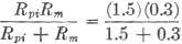
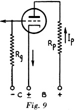 Example: In the case of Fig. 9,
it is assumed that the grid is to be fed a square-wave pulse. Compare the plate
voltage when the tube is conducting a current of 15 ma. with the effective plate
voltage when the tube is idle and not drawing plate current. The plate resistance
is 10,000 ohms.
Example: In the case of Fig. 9,
it is assumed that the grid is to be fed a square-wave pulse. Compare the plate
voltage when the tube is conducting a current of 15 ma. with the effective plate
voltage when the tube is idle and not drawing plate current. The plate resistance
is 10,000 ohms.