Winning the National Radio Control Meet
|
|
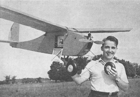
You might wonder why an article entitled "Winning the National Radio Control Meet" for model airplanes would appear in the ARRL's QST magazine. The answer is that back in 1940 when it was published, a Ham license was required to operate a radio control (R/C) transmitter. There were no license-free bands for hobbyists as there are now. In fact, it wasn't until 1976 that the FCC (Federal Communications Commission) suspended their requirement for registration as an operator, which has returned in the form of an FAA (Federal Aviation Administration) "drone" (aka USAS) pilot directive. The author, William (Bill) E. Good (W8IFD, W2CVI), was the twin brother of Walter (Walt) A. Good (W3NPS), both of whom held doctoral degrees in and physics, and were referred to as "the fathers of radio control." The photo of Bill shows his station identification (W8IFD) displayed on the transmitter enclosure, as required by the FCC. Bill's son, Gary, was also a Ham (N2BLZ). They were born in 1916 and won the R/C championship in 1949, at the age of 33. In the early days, R/C operators built - and often designed - their systems, including the electronics and mechanics. They were the pioneers that took the figurative arrows while forging the frontiers of this hobby. Here is a video honoring the Good Brothers. A couple notable items mentioned in the article are the needing a QSA "5" level signal (the highest quality of reception) in order to assure reliable control of the aircraft, and of how Hams helped advance the design of small internal combustion engines. Also, Fig. 4 shows the rudder escapement located in the vertical fin, with the wound rubber there as well. Winning the National Radio Control Meet
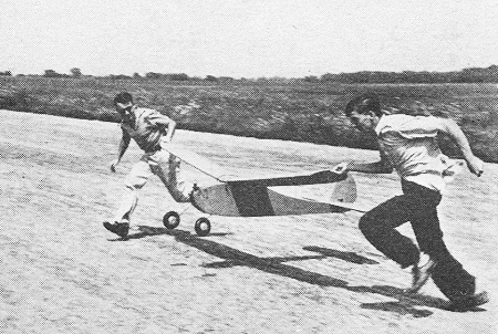
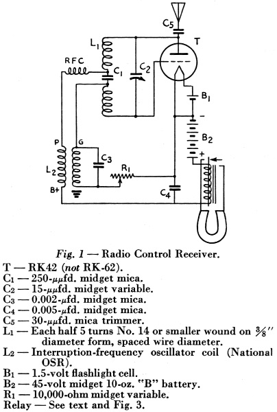
The take-off! Practically all flights are made in this manner to ensure good take-offs despite the man at the controls. The plane is being guided, not lifted. Details of a Radio-Controlled Model Airplane That Has Made Over One Hundred Successful Flights By Wm. E. Good,* W8IFD Four years ago a radio-control event was added to the program of the annual National Model Aircraft Championship Meet. But it was not until last year that a wholly successful demonstration of radio-controlled flight under a variety of conditions was finally achieved. The Good brothers of Kalamazoo were responsible, their triumph climaxing years of experimentation. Here is the story of their Success. One of the most interesting by-products of ham radio is that of radio control of gasoline-powered model airplanes. Here is one sport where your signals must be QSA 5 or you may have to start on a cross-country jaunt, praying that those two ounces of gasoline will hurry up and run out. If your signals are "getting through," you find yourself landing the radio-controlled plane right in the middle of the runway. Exciting? I'll say! Every flight is just like that memorable first QSO! Radio control of model planes began with the advent of small gasoline motors and has been progressing slowly ever since. Most of the development has been done by hams in cooperation with the gas model enthusiasts.1 Our equipment is the result of over four years' experimentation and of late has proved rather successful. The control consists of two frequency channels - one for the rudder and the other for the elevator. For each channel there is a modified five-meter superregenerative receiver. In its plate circuit is a sensitive relay which is connected to an electromagnetically-operated rubber-powered escapement in the tail which moves the controlling surface in the fashion desired.
Fig. 1 - Radio Control Receiver. The plane, designed and built by my twin brother Walter, has an 8-foot wing span and weighs slightly over eight pounds, including its two pounds of radio gear. Its gasoline motor is of the one-fifth horsepower variety and does a good job of flying this stable ship. The cruising speed is about 20 miles per hour and the ship glides very well, insuring excellent landings if reasonable skill is used at the controls. The plane banks automatically when the rudder is turned, due to the dihedral in the main wing. Before a flight the receiver in each channel in the plane is adjusted so that its sensitive relay closes when the carrier from the five-meter transmitter is turned on. The sensitive-relay contacts actuate the small electromagnet (in the tail) which allows the rubber-powered escapement wheel to go through one position or one-quarter of a revolution at a time (i.e., for each dash sent). The controlling surface is connected directly by a small steel-wire arm to a pin on the escapement wheel. The power used to move the surface through its positions is taken from the wound-up rubber band. Our control surfaces have three main positions, e.g., the rudder has left, neutral and right, plus two half or intermediate positions, making five in all. Naturally, the movements take place in a cyclic fashion. Each pulse or dash from the transmitter causes the surface to move from one main position to the next. Walter has done practically all of the design and detail work on the escapements and the sensitive relays, although he's not even a ham. We did have him in the RI's office one Saturday morning to take his exam - but he sneaked out and made the rounds of the model airplane shops in Chicago! Escapements Located in Tail The escapement units in their present state weigh just a half-ounce each and are mounted permanently in the tail surfaces, so that direct mechanical connection can be made to the moving elements (rudder and elevator). This makes for extreme reliability in addition to the fact that the units boast almost instantaneous response, which has been shown to be practically a necessity under actual flying conditions. A control stick or "joy stick" (one for each control) which adapts itself very well to the escapements is a Western Electric telephone switch which was rebuilt so that contact is made and broken (sending a dash) as the switch is moved from neutral to either extreme position. Thus the rudder or elevator will be in the same position as its corresponding control "stick," and this synchronization will be maintained as long as the control switches are moved through complete cycles. The moving elements will follow the motions of the switches even though they are jerked back and forth as fast as four or five times a second. Thus the surface may be moved to any desired position with such rapidity that the motion of the plane is not affected while so doing. Due to the arrangement of the switches and the tail escapements, the corresponding moving element will be in a half or intermediate position when its control switch is in a half position. This system allows the operator to know exactly where the rudder and elevator are positioned at any instant. Actual flying has shown this to be a natural method of control.
Bill Good, W8IFD, with the fuselage and ground control set-up. Left, the genemotor and its battery box; center, the two-frequency transmitter in its travelling case; lower right, the control box with two telephone-type switches as joy sticks.
Ready to fly! Walter Good, national radio-control champion, holding his winning ship. The receiver is accessible through the open doorway in the side of the cabin.
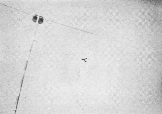
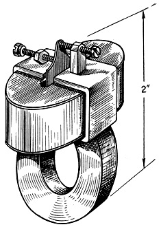
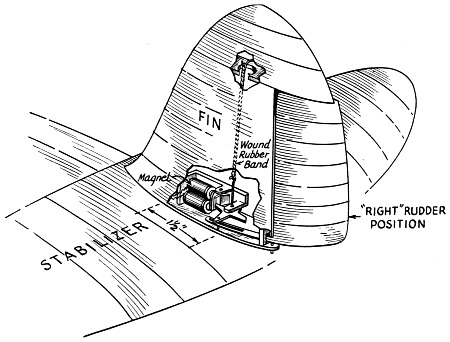
In flight! Framed by the center-fed doublet atop a bamboo mast, the ship is but a speck in the sky. The radio controls operate as far as the ship can be seen. The sensitive relays have been the result of a generous mixture of theory and experiment on the ground and in the air. In all, six relays have been developed. The one that has proved the most satisfactory and the one that we have been using for the past two years we call the DG-6. (It can be duplicated for fifty cents.) It is a polarized balanced-armature type (no springs), weighing two ounces, and operates on less than one milliwatt. For vibrating motors and airplanes in flight we believe this is the Good answer to the maiden's prayer! The receivers have also had their share of attention, and considerable research has been done to find the best operating conditions. Essentially they are one-tube superregenerative jobs in the self-quenching circuit using quench coils, but the conditions of operation have been changed so that a maximum change in plate current takes place when a signal is received. A Type 30 tube will give a plate current change of as much as three milliamperes, while an RK42 (a 1.5-volt version of the 30) will give about two milliamperes change (through 2500 ohms). Besides the tuning condenser, the antenna padder and the grid bias resistor are adjusted to obtain maximum plate current change. On the field it is only occasionally necessary to adjust the variable grid resistor. Experimenting has been done with various circuit constants and different makes of quench coils in addition to different quench frequencies and quench voltages. By extending the recently developed superregeneration theory, it is not difficult to explain the theoretical basis for the required adjustments. The Two-Frequency Transmitter The transmitter is unique in several ways besides portability - if you call lugging a six-volt storage battery portability! It utilizes two separate electron-coupled oscillators (one frequency for each channel) and only one final amplifier. The two 6V6G e.c.o.'s have a common plate tank - which, by the way, works very well - broadly tuned and capacity coupled to the 807 doubler-final. The half-wave horizontal center fed Hertz antenna is furnished r.f. by a tuned line which is inductively coupled to the final. A switch is incorporated to remove the power from the 807, leaving just the weak five-meter harmonics from the e.c.o.'s for tuning the receivers when the plane is near the transmitter. The genemotor mounted on top of the storage battery is a 400-volt 125-ma. job. Nevertheless, only 20 to 30 watts of the fifty available is the accustomed power input. This polarized relay, designed and built by Walter Good, is of the balanced armature type, having no springs on the armature. A small Alnico horseshoe magnet holds the thin iron armature against the back contact until the coil and its surrounding soft-iron magnetic circuit is energized. With a 2500-obm coil the reliable sensitivity is 1 milliwatt. The weight is slightly over 2 oz. When the plane is properly adjusted it flies and glides straight with the neutral rudder position and gives the same size circles to the right or left for the extreme positions. This is true both under power and in the glide because of proper power and wing loading. A great deal of flying is done with the rudder alone. For this, the elevator is adjusted for a good climb and then it maintains level flight in the turns. Theoretically, the gyroscopic effect of the motor should cause the nose of the plane to come up when the plane is turned left and down when turned right, but practically this effect is not noticeable. The small control escapement is considerably exaggerated in size to show detail. Actually the small magnet coils are about 1/4" diameter and each escapement weighs about 1/2 oz. The elevator control escapement is similar, being located in the stabilizer just to the right of the fin juncture. When the rudder is turned to either right or left maximum position, the plane banks automatically and proceeds to execute a beautiful right or left circle. If the control is kept in this position for more than one turn or so, the bank gradually becomes steeper and the turn develops into a large spiral. It is not difficult to lose any amount of altitude in short order by spiraling the ship down in this manner, even if it is only for the gratifying sensation of pushing the control stick neutral to watch the plane straighten out and start into a fast climb, using up the speed just acquired by the descent.
The receiver in its balsa-wood container, with the battery supply underneath. The miniature polarized relay can be seen in detail. Batteries are attached rigidly to the fuselage, hut the receiver is mounted in sponge rubber and suspended by rubber bands.
Fig. 2 - The Two-Frequency R/C Transmitter.
Fig. 3 - The DG-6 Sensitive Relay.
Fig. 4 - Isometric View of the Tail Assembly in the Good Championship Plane. One question that always arises in radio control discussions is, "Is it necessary to have such speedy snap-action controls?" In our flying we have found that fast control has been more than convenient, especially in take-offs and landings. Many times in coming in for a landing it has been imperative to give opposite rudder to straighten out the glide when the ship was only four or five feet from the ground. A second of time in such a predicament is precious. Take-offs call for more precision and speed of control, because the controls are more sensitive and the operator really has to have the "feel" of the controls to keep the plane right-side up. The picture shows the usual take-off procedure of running the wing tips until the plane is well off the ground. We've found it's much safer to learn how to "fly" after the plane is up in the air! Lately, however, we have been merely starting the plane down the runway (tail off, but wheels still touching) and keeping it as straight as possible with the rudder control. Strangely enough, when the plane starts towards the edge of the runway (and it usually does) plenty of control is needed instantly to bring it back and then care must be taken not to over-control. Thrilling? Yes! But if you control wrongly a wing tip starts digging up the runway or vice versa! The National Championship Meet In winning the Radio Control event at the National Model Airplane Contest at Detroit this year, the radio and the plane performed in grand style. The radio-control planes were judged on their ability to execute a number of pre-decided maneuvers. The best flight we had lasted about 14 minutes. The ship climbed to approximately 1500 feet during the six minutes the motor was running. During the first part of the flight the model was sent down-wind to a field-light objective about one-quarter of a mile away, following the judge's instructions, and then was turned around and brought back over the transmitter. As you can see, this is an excellent stunt really to test the controllability of the model. Next, as we usually do, the plane was guided up-wind and the rest of the flight consisted of right and left circles, figure eights and the like, on command of the judge. At the end of this particular flight the job was landed about a hundred feet from the transmitter, thus establishing the first real radio-controlled flight at a National Contest. Will any transmitter work the control? Yes, anyone that's on the right frequency in the five-meter band. The five-meter gang from Detroit was on hand at the Nationals to help with the radio-control event and their main transmitter - a portable-mobile outfit - operated our controls very effectively. However, the cooperation between the contestants and operators was very gratifying and for the most part no interference resulted. The only case of interference we've had in over a hundred flights this year and about fifty flights last year occurred in Chicago during a demonstration at the big Mid-Western States gas-model contest. We had flown the job in a strong wind in the morning and Walter had succeeded in landing the plane within two feet of the point where the wheels had left the ground on the take-off! Naturally, feeling so confident about the success in such windy weather, we decided to send her up again in the afternoon. It was my turn to "fly." Everything went fine until about thirty seconds after the motor cut, when the plane refused to respond any more - 1200 feet up, slightly up-wind and a 15-mile "breeze" blowing! Nothing we did on the ground had any effect - the plane was making great progress cross-country in a large circle, indicating half rudder position. Possibly another five-meter carrier was holding the relay down? The plane eventually landed about a mile and a half away and was finally recovered - but that's another story. The controls were checked and found to be in working order, leaving us with only one conclusion - that some amateur in the Chicago area was operating on the same frequency! (Time of flight, 4 P.M., Aug. 6, 1939.) This system of control has worked as long as the plane has been in sight - about two miles. So far we've found no reason for flying it at a greater distance than that, especially when our original purpose was to bring the model back to the field so we wouldn't have to chase it! This plane has done itself proud by winning the "Nationals" two years in a row, by taking the radio-control event in Chicago, by receiving first place in the original-design event at the Scripps-Howard Junior Air Races at Akron, by being possibly the first radio-controlled plane to be flown in Canada through a number of flights made at the Canadian National Contest at Toronto, and finally by its good behavior during demonstration flights at contests around Michigan. We hope we've worked up your enthusiasm so that you may join this exciting diversion of amateur radio. All bragging aside, it's not easy, but, boy - it's lots of fun! * 934 Hillcrest St., Kalamazoo, Mich. 1 QST, Oct. 1937 and June, Sept. and Oct. 1938; Model Airplane News, January and August, 1938; Air Trails, August 1938, January and May, 1939.
Posted April 8, 2023 |
|