Magnetic Ceramics: Ferrites
|
|
Magnetic ceramics have been with us for a long time - probably forever as far as most people that use them these days are concerned. When this article was published in a 1953 issue of QST magazine, ferrites for use at RF frequencies were a new, breakthrough phenomenon. Take a look at inductors used in vintage radio equipment and you will find either air or solid iron as the permeable filler elements in most instances. Whereas iron might have a permeability of 100-150, the new magnetic ceramics exhibited permeabilities up to 4,000 at 1 MHz, and even higher for lower frequencies. Modern alloys and compounds provide permeabilities of more than 50,000 for special applications. Such high values allow physical size and weight of inductors and transformers to be greatly reduced. Also, since high permeability does a better job of constraining magnetic fields within their geometries, less shielding is required to prevent crosstalk. A plethora of resources are available on the Internet for design guidelines. Magnetic Ceramics: Ferrites The Latest in Magnetic Materials for R.F. By F. E. Vinal, W1GXJ
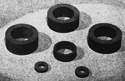
Typical ferrite cores for toroidal inductors. (Photo courtesy Sprague Products Co.) Through current advertising items and several articles which have appeared recently, some in electronics journals, it is becoming increasingly evident that an entirely new series of electronic components exists based on the magnetic ceramics or ferrites. These materials, many of whose trade names have been obtained by taking various liberties with the Latin word for iron - ferrum - have opened new horizons for the professional design engineer, but they are no less a challenge to amateur ingenuity and the home experimenter. It is the purpose of this article to introduce magnetic ceramics to the rank and file of the amateur fraternity; from there, one hesitates to predict what may result. No attempt will be made to be fundamental about the source of the magnetic effects. The writer, who is a chemist gone astray, does not follow all of the abstractions which are available on the internal workings of atoms, but friends who are theoretical physicists tell me that quantum mechanics are required to give an adequate explanation of the origin of the magnetic effects in ferrites; further, there are adequate theoretical publications now available dealing with these phenomena in ferrites. Let us see instead what ferrites can mean to those who get their callouses handling the soldering iron. First, one might ask, "Why ferrites?" Refreshing our memories from what the ham's bible (29th edition, 1952, page 27) has to say about iron-core coils and their properties, we can conclude that where currents run small - as in r.f. or i.f. transformer windings for receivers - it would be very helpful to have high-permeability, low-loss cores. For this purpose, component manufacturers have provided powdered-iron cores which have permeabilities of the order of 125. Powdered-iron cores offer great improvement at low and intermediate frequencies, but at the high frequencies losses still plague us and the effective permeability of a powdered-iron slug is far below the true permeability which may be obtained with a closed magnetic circuit (toroidal cores). Now come the ferrites with maximum permeabilities ranging up to 4000 at 1 megacycle and with a loss factor of 0.0003 at that frequency. With further increase in frequency, the path divides at present into high-permeability materials with rapidly increasing losses and lower-loss materials of much lower permeability. The field is an active one and advances are being made daily, so it would be foolish to assume nothing better is forthcoming - but just how soon would be hard to say: Where the Losses Come From High permeability and low losses in the r.f. range! How do we get it? Well, first let us borrow a formula from the metallic-iron core designer. From it we can say that the eddy-current losses (which are the principal losses to be considered) for each lamination in the core are dependent upon a number of factors, some of which we can monkey with and some of which we cannot:
where A = V = volume of the lamination Bmax = magnetic flux in the lamination d = thickness of the lamination ƒ = frequency R = specific resistance of the lamination Frequency and thickness both occur in the numerator as the square power and work against you, and volume should be kept as low as possible. You can't help wanting to use high-permeability material at high frequencies but what can you do about the thickness? There is practical limitation to minimum thickness for a single lamination, and to exceed that limit core manufacturers have turned to finely-powdered iron particles. However, these cannot be packed together without insulating them from each other, just as the laminations in a power transformer are coated with a film of shellac. Plastics have been used to coat the powdered-iron particles, but the amount of plastic necessary to coat completely the surface of each iron particle becomes surprisingly large in these particle size ranges. To get some idea of the surface area involved, start with a centimeter cube whose surface area is 6 square centimeters. This amount of material, if reshaped, would be approximately equal to one i.f. tuning slug. Cut it first into 8 equal cubes, one-half centimeter on an edge, and the surface area has increased to 12 square centimeters. Continuing to cut, we find that after 1000 cuts the surface area is 60 square centimeters and when the cubes are a millionth of a meter on an edge, the total surface is 60,000 square centimeters or 64.5 square feet. The amount of plastic insulation present in a powdered-iron core is therefore considerable, and its principal effect is to "dilute" the iron and hence lower the overall true permeability to about 125 from a value of 2500, typical for transformer iron. Worse yet, even these small particles develop losses that can, at high frequencies, become serious or prohibitive. Permeability decreases further because these fine-grained materials have higher coercive force values, and as the area enclosed by the hysteresis loop increases, so do the hysteresis losses. The use of open magnetic circuits (slugs) instead of closed magnetic circuits (toroids) takes away a considerable chunk of the true permeability, so that at 100 Mc. one can expect an effective working permeability of about 5. Referring back to the formula, the denominator is seen to contain the specific resistance of the core material. For iron (no matter how small the particles may be) this figure is about 0.00001. Dividing an already large numerator by such a figure makes the answer come out extravagantly large, and there is no way to change this materially so long as you are dealing with iron and its alloys; it's just the nature of the beast. Get acquainted with one of the newer magnetic materials that looks destined to play an important part in the communications field. It is already responsible for some of the high-Q coils that have gone into low-frequency "super-selective" i.f. amplifiers. Why Ferrites Are Better
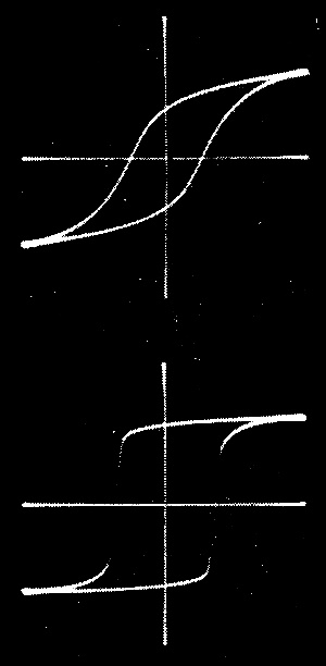
Oscillograms showing the types of hysteresis loops obtained with ferrites. The flattened top and bottom of the lower trace show a type of characteristic that lends itself well to on-off magnetic switching circuits. Ferrites, however, are different. The various commercially available types have specific resistance values ranging from 10,000 to 1,000,000,000 ohms per centimeter cube. With this sort of figure in the denominator we no longer care about the thickness, d. We can make the core of one solid piece to achieve maximum working permeability and take full advantage of the magnetic properties, at least up to moderate frequencies. Although V increases, this is more than offset by high specific resistance values in the denominator. At present, materials for use at 3 to 5 Mc. are available which have low loss and high permeabilities (700-800). Toroidal coil forms of this material should provide the highest efficiency yet achieved in transformers for this range and perhaps the next 5 or 10 Mc. as well, for although losses increase rapidly with frequency, they don't go out of sight yet. Many problems remain to be solved, but ferrites offer more promise for r.f. cores than any material known. At the very high frequencies, dielectric losses in ferrites become quite high and we do not yet have the answer to very good cores for use above 10 to 20 Mc.; but, even so, those now available are fully equal to or superior to powdered iron at 100 Mc. As we go from the very high to the ultrahigh range, oddly enough the dielectric losses largely disappear in the range of 500 Mc. for some of the ferrites. Above that, these materials are rather free of loss up to the range of 12,000 Mc., with the exception of a range around 3000-4000 Mc. where large losses occur from magnetic resonances within the crystal lattice structure of the materials.2 This figure is variable and may be adjusted to lie outside a desired operating range. What They Are A few words about the composition and manufacture of ferrites may be of interest. First of all, it has been found that a few simple inorganic chemical compounds, known as ferrites, are magnetic (there are many other ferrites which are not magnetic). The basic ideas are not new, as they are a logical extension and expansion based on the magnetic lodestone whose origin is lost in Chinese antiquity. Hence, one could easily say, "Why didn't I think of that?" Be that as it may, it was not until about 1935 that any systematic studies were undertaken toward the results we now have available. Commercially, the development is entirely a postwar one. Magnetic ferrites are formed by chemical reaction of one or more oxides of certain metals with a chemically equivalent amount of red oxide of iron. This reaction is usually carried out between the mixed oxide powders at temperatures above 2000° F. The various metal oxides which may be reacted with red oxide of iron are magnesium oxide, black oxide of iron (which results in magnetite or the lodestone), nickel oxide, copper oxide, cobalt oxide, manganese oxide and lithium oxide. These combinations will each give a simple magnetic ferrite. However, complex mixtures of oxides are usually employed, in order to give improved or special properties to the ferrite. Oxides of zinc and cadmium form nonmagnetic ferrites, but are often blended with the magnetic ones to reduce the temperature at which maximum permeability occurs to a value near normal operating temperature. Once the oxides have been reacted, the ferrite powder thus formed is used to shape the piece or core desired. The usual practice is to mix a little binder with the powdered ferrite and then press the desired piece in steel dies. The piece thus formed will hang together until placed in a furnace for the final hardening or sintering process. During the early stages of this heating, the binder is burned out of the piece and later, at temperatures above 2000° F., the particles sinter or coalesce into a dense, hard, somewhat brittle material, usually dark in color. Applications and Possibilities Ferrites have already seen many applications, and new ones are coming up practically daily. Some of the better known applications see them used in recording heads, i.f. transformer cores, magnetic modulators, horizontal sweep output transformer cores for TV, yoke cores for TV, audio transformer cores (fine for the very high audio frequencies), tuning slugs, "built-in" antennas, electronic computer "memory devices," pulse transformer cores, recording tape coatings, etc. One of the most intriguing uses proposed is the microwave gyrator. In this application, a rod of ferrite is inserted axially in a wave-guide where a polarized microwave may be rotated up to 90° upon passing through the ferrite in one direction but a reflected wave is rotated 90° again in the same direction and hence it is possible to isolate an oscillator or some other associated device from the rest of the microwave system.2 The limit to which ferrites may be applied is not now known, and it is not possible even to speculate on it because of the continuous march of new ideas as the properties of ferrites are further explored. For instance, it has been found that the shapes of the hysteresis loops of ferrites can be monkeyed with (see photograph) on a practical basis. The two hysteresis loops shown are for specimens prepared by the author, and yet the chemical analysis of both specimens is the same. Fast-switching ferrites suggest magnetic switches which will operate in 1 or 2 microseconds, and many other interesting possibilities. Now it's up to you to try ferrites in your pet circuit or scheme and see what comes of it. Who knows - you might make a million dollars! Editor's Note: Ferrite parts are being produced by General Ceramics & Steatite Corp., Keasbey, N. J.; Stackpole Carbon Co., St. Mary's, Pa.; Ferroxcube Corp. of America, Saugerties, N. Y.; but all current production is of manufacturers' items only, It is expected that Ferroxcube Corp., through its affiliate, the Sprague Products Co., North Adams, Mass., will soon make ferrite parts available through regular distributors. 1 Magnetic Circuits and Transformers, M.LT. Staff, p. 136, J. Wiley and Sons, 1943. 2 Bell System Technical Journal, Vol. 31, pp. 1-31, 1952.
Posted October 11, 2023 |
|

 , a constant