Harmonic Radiation from External Nonlinear Systems |
|
My introduction to passive intermodulation (PIM) issues was while working on a BTS switching system back around the turn of the century (yes, this century), where because of high power levels, the matrix had to be guaranteed to not generate PIM products greater than a certain value. About 1/3 of the units were not passing test. The cause turned out to be a high power attenuator in one of the paths. The manufacturer of the attenuator was a very well established and reputable firm. The PIM levels were intermittent and would come and go after removing and then replacing the interconnecting cables. I fortunately noticed that the N-type connector on one end of the attenuator was rotating slightly during the process. According to our specification to the manufacturer (it was a custom design), the connector bodies were to be pinned to prevent movement during torqueing. They appeared to be built properly because the small hole where the steel pin was driven had been backfilled with conductive epoxy. When the company was told that the connectors were rotating, they immediately blamed us (me, actually) for abusing the connectors, since there was no way the connectors would move with the pins in place. I shipped some of the failed units back to them, received replacements, and darned if some of the new ones didn't do the same thing. Again I was blamed, since the QA inspection paperwork "proved" the connectors had been pinned by virtue of the stamp at that process step. I was sweating big time by then, but knew I had not abused the attenuators. Fortunately, the company I worked for had an x-ray inspection machine, so I took a good and a bad attenuator to the shop and had the technician have a look inside. Guess what? That's right, no steel pin was visible in the bad attenuator. All of the failed units were x-rayed and shown to be missing the pins. The carefully documented QA process of the supplier had been fudged. I'm not sure what happened to the people responsible there, but I imagine it was not a happy time since they had been so arrogant and adamant toward me. Bullet dodged. Harmonic Radiation from External Nonlinear Systems
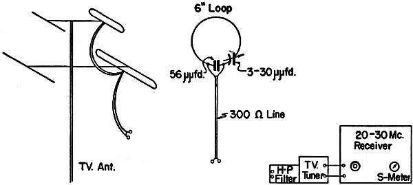
Fig. 1 - Double-conversion arrangement for identifying and measuring harmonic signals. Sources, Characteristics, and Methods of Detection By Mack Seybold,* W2RYI This article is the first comprehensive treatment of a type of harmonic generation that represents the last barrier - and often a nasty one - to completely TVI-proof operation in fringe areas. When shielding and filtering on the transmitter, and high-pass filters on the TV receiver don't do a complete job, external rectification is the probable reason. The author, an outstanding worker in the anti-TVI field from the beginning of post-war TV broadcasting, presents here the results of a thorough study of the problem and describes new methods for its detection and elimination. The old filter-builder, Ralph, W2CVF, had been passing comments during many sessions of the Gloater's Club. Most of the boys on the 29-Mc. net were right in there pitching with him: "How can a guy spend two or three years out there in West Orange chasing microvolts with a butterfly net!" Or, "All you have to do down here in Englewood is put the rig and filter in a couple of dishpans back-to-back, and you're on the air! Why fiddle with the plumbing in the kitchen sink?" Ralph would agree that there was a remote possibility that sinks might be involved in TVI. We all would agree that some sinks might be above suspicion, but, of course, there are different kinds of sinks - big ones and little ones, clean ones and rusty ones, city sinks and country sinks. It finally took Santa Claus to get Ralph to believe in kitchen sinks. On Christmas Day, in 1951, W2CVF went on the air to pass along his season's greetings and to find out who had been able to cash in on the softened-up holiday atmosphere for double-conversion superhets. The atmosphere didn't stay soft for long in West Englewood that day, however. Channel 2 was taking a beating from the most filtered transmitter east of the Hackensack. How could a horrible thing like this happen to an ardent disciple of Phil Rand, Russ Valentine, and George Grammer? How could it happen to the chief baiter of K2CR and W2RYI for bigger and better filter designs? Ralph admits that he remembered the kitchen sink as soon as the unusual occurred. Actually, the plumbing wasn't involved, but it was the same proposition in a more refined category. Santa Claus had seen to that! The most recent change in the household was a Christmas present to the up-and-coming junior operator, a crystal set for the pleasure of a Christmas toy, and possibly the beginning; of a devious road to scientific achievement or fun and fortune on the amateur bands. No sweeter demonstration of nonlinear systems could have been prepared on the laboratory work bench: a 29-Mc. harmonic-free transmitter, an efficient crystal rectifier on an isolated receiving antenna, and a television set tuned to a holiday show. Ralph suspected the crystal and, sure enough, when the cat's-whisker was lifted from the galena, TVI ceased entirely. Case Histories
Table I - TVI from Nonlinear Systems Table I lists some of the many sources from which harmonics produced in external nonlinear devices were strong enough to interfere with television reception. There are probably hundreds of locations where harmonics are produced at a level too low to develop visible cross-hatching, but are strong enough to measure with simple equipment. From the evidence at hand, it is somewhat perplexing that more of the interfering variety have not been reported. Perhaps, in time, some of the low-level producers will develop into efficient rectifiers, and stronger harmonics will be radiated. This development may be particularly noticeable in cases similar to the one listed in the table wherein corroded TV antenna fittings were found to be at fault. Corrosion conditions are accelerated in humid regions, especially where salt pray is in the atmosphere. Some industrial centers have a slightly acidic atmosphere, which also enhances corrosion. Signal Strength for Interference As usual with TVI problems, a harmonic entering a receiver at a frequency near that of the picture carrier will not produce cross-hatching unless it is at least 1/100 as strong as the TV carrier. A harmonic measuring 100 microvolts at TV-antenna terminals might never be seen on a kinescope located within walking distance of a TV transmitter. The same level of harmonic measured at a fringe-area receiver, however, could very well be equal in strength to the picture carrier, and could produce cross-hatching as black and white as the picture elements. If all amateur transmitters were completely single-signal radiators, the fringe-area boys would still have more TVI problems than the amateurs in the primary coverage areas, because harmonics from external rectifiers are produced with equal facility in both areas. Basically, any rectifier can produce harmonics if a signal is fed to the cathode-anode circuit. The low-order harmonics are the strongest, and the high-order harmonics become progressively weaker unless some common resonant circuit accentuates a specific multiple of the fundamental frequency. A good rectifier is one which has the largest ratio of forward-to-reverse-direction current flow. A device having a low rectification ratio will be less efficient as a harmonic producer, the ultimate being a pure conductor which passes current equally well in both directions, producing no harmonics, or a nonconductor which will not pass current in either direction. TVI from Nonlinear Systems
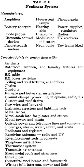
Table II - Nonlinear Systems Rectifiers are called nonlinear devices because of the marked discontinuity in the graphic presentation of their conduction characteristics. Triodes and pentodes are also nonlinear devices because the output is not exactly proportional to the input, and a graph illustrating the operating characteristics discloses a curved line. The range in which an amplifier is normally used is represented by such a limited portion of the curve that it is almost a straight line, and the harmonic output is extremely low. If the range is increased by applying a large input signal, the portion of the curve used no longer approximates a straight line, and the output signal, therefore, is not an exact reproduction of the input signal. The resultant wave-shape is a composite of strong harmonics. Natural-Born Rectifiers Nature is a prolific producer of rectifiers. Oxides and other corrosion products of metals will frequently pass current better in one direction than in the reverse. The efficiency of most of these compounds is low, but some of nature's products are excellent rectifiers. Lead sulphide is the galena crystal of early radio fame. Silicon and germanium diodes are employed in many modern applications. Copper oxide and selenium, produced under controlled conditions, are utilized extensively for power rectification. Because corrosion of such metals as iron, copper, and aluminum proceeds uncontrolled in nature, the rectification ability of the corrosion by-products from these metals varies immensely. If the material can pass current slightly better in one direction, however, and if it is part of a circuit arrangement in which r.f. signals can be admitted and released, harmonics will be produced. The strength of the harmonic is a function of the r.f. voltage applied, the efficiency of the rectifier, and the resonant frequency of the system. All of the elements required to produce a harmonic-generating system are present in the houses and structures in the vicinity of amateur stations. If a house could be observed with Superman's X-ray eyes, the metallic structure standing there would be identical to the conductors that a radio wave would recognize as it passes through the maze of pipes, wires, ducts, and fixtures. An r.f. signal produces standing waves on the various elements of this complex receiving antenna, and wherever a rusty or corroded joint has formed between pipes or lines crossing each other, rectification takes place. The harmonics produced are reradiated by the same metallic maze. If a joint is an efficient rectifier, if the r.f. voltage applied is high enough, and if the resonant frequency of the metallic structure is appropriate, a nearby TV antenna may receive a harmonic signal sufficiently strong to interfere with the picture. The poker joint listed in Table I produced a 1000-microvolt 57-Mc. signal on the feeder of a TV antenna located 30 feet from the joint and 80 feet from the 28.5-Mc. transmitting antenna. Because manufactured rectifiers are usually the most efficient, any equipment containing them may be suspected of producing harmonics. The access of r.f. signal to equipment rectifiers is the limiting factor in TVI production. Other tubes, vacuum and gas, triodes and pentodes, can also produce harmonics if sufficient r.f. reaches them in the equipment suspected. Locating Nonlinear Devices
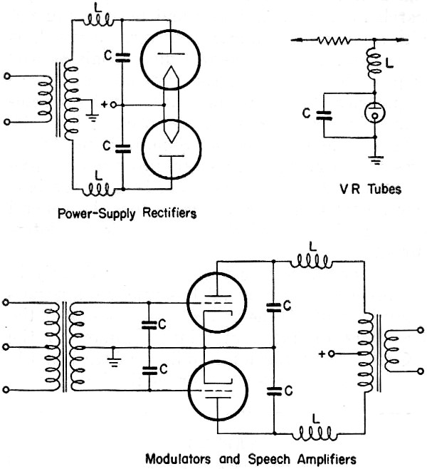
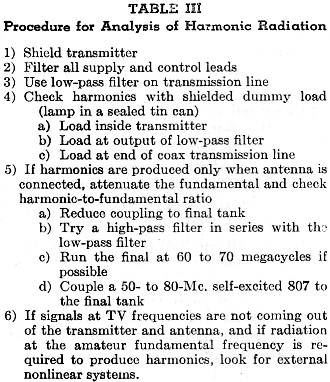
Fig. 2 - Bypass filters for exposed tube circuits where rectification can occur. L = 30 μh.; C = 1000 μμfd. Table II lists some of the places where trouble may be encountered. Locating natural nonlinear joints is sometimes difficult. Watching the interference pattern on a TV receiver while pushing exposed pipes, air ducts, BX cables, etc., may disclose the location of a joint. The intensity of the interference changes rapidly as the joint is jarred by pushing the pipe or pounding the floor or "all behind it. When brute-force methods fail, more exacting techniques are required, especially when the system is located between floor and ceiling, or sealed behind plaster walls. Fig. 1 shows a 6-inch pick-up loop fed into a TV tuner. Readings are taken on the S-meter of the communications receiver tuned to the output of the tuner. As a joint is approached with the loop, the S-meter on this double-conversion equipment will indicate an increase in signal strength. The loop will not always pin-point the source, however, because the harmonic signal may be radiating from a considerable length of metal, such as pipe or BX. comprising the joint circuit. As a matter of fact, the complexity of the circuits involved led to the experiments at W2RYI to learn more about the behavior of harmonic-producing joints. If a nonlinear system cannot be located by direct methods, knowledge of its characteristics is helpful in the detective work necessary to isolate and eliminate the source of the trouble. The groundwork for these experiments had been laid in 1947, '48, and '49; completely shielded transmitters and conservatively designed low-pass filters were used, and the worst of the natural nonlinear systems were eliminated. All vacuum and gas tubes in exposed power supplies and control circuits had been by-passed, as shown in Fig. 2 and Table III. Some of the preliminary search for nonlinear joints had been conducted with a portable broadcast receiver. Inasmuch as these external rectifiers will mix signals as well as produce harmonics, the sum and difference frequencies of two signals transmitted from antennas in the back yard are produced in the nonlinear house circuits. Simultaneous transmissions on 27.0 and 28.4 Mc. produced a 1400-kc. signal which could be picked up on the battery portable. In this instance, too, the general location of the rectifying joint could be determined.
Table III - Procedure for Analysis of Harmonic Radiation Another phenomenon proved helpful early in the proceedings. A small 60-cycle voltage normally present on the BX sheath modulated the harmonics produced in joints common to the BX cable, and the hum could be heard in the double-conversion set-up or could be seen as horizontal bands having variable intensity in the interference pattern. Joints common to water and gas pipes did not exhibit the modulation, so one more bit of information was available to aid in isolating rectifiers. Eliminating Joints Several techniques were used at W2RYI to eliminate nonlinear joints after they had been located. When possible, the junction was insulated or separated mechanically. Several BX-box connectors had to be scraped and soldered. The water connections to the kitchen sink were inaccessible, and neither insulating nor soldering could be accomplished without ripping up the wall, so a third method was required. Where the pipes emerged under the sink, short copper straps were connected to by-pass the iron-enamel-rust pipe junction. How long can an effective shorting strap be? How far away from the transmitter can difficulties be expected from harmonics produced by nonlinear systems? What effect does pipe length have on production and radiation of harmonics? Does a joint produce harmonics in direct proportion to transmitter-power input? These were some of the questions that needed answers in the form of specific data, and the experiments were performed to obtain those data. Tests with Artificial Joints A 1N34 crystal diode was utilized to simulate a relatively efficient rectifying joint. The measurements were taken on the double-conversion set-up after it was calibrated with a borrowed signal generator; a well-filtered TV receiver was used to reveal the interference effects. The receiving antenna used for the measurements was of the high-band, low-band type, with folded dipoles and reflectors. This antenna was located 15 feet off the ground and 50 feet from the discone transmitting antenna. The artificial nonlinear systems were also placed 50 feet from the discone, and were located 20 feet behind the TV antenna. The picture carriers of Channels 2, 4, and 5 from New York averaged 1000 microvolts at the feeder terminals while measurements were being taken, which makes the threshold of interference with this particular set-up approximately 10 microvolts.
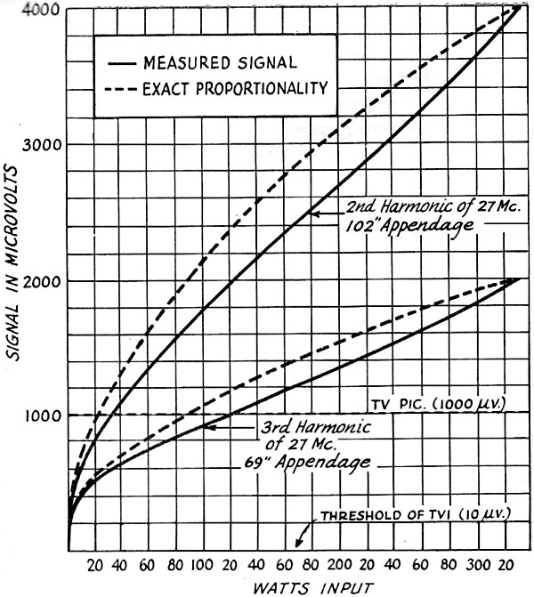
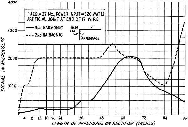
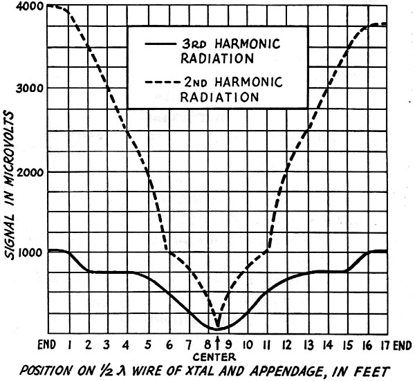
Fig. 3 - Effect of power input on harmonics produced by artificial joint. Fig. 3 shows the effect of transmitter power input upon harmonic output of the 1N34 system. The dotted lines represent exact proportionality between transmitter power input and harmonic signal output. The deviation exhibited is small enough to indicate that the measurements were reasonably accurate and that the voltages applied to the crystal were not causing breakdown or saturation. Extrapolation of the data for these curves shows that the power input to the final amplifier would have to be reduced to 0.003 watt to stay below the threshold of interference with an isolated nonlinear system of this efficiency. Fig. 4 shows the effect of various lengths of wire connected to the crystal diode. Here, as in Fig. 3, the rectifier was placed at the end of a half-wave conductor, but the wire appendage connected to the other diode terminal was shortened progressively as the readings were taken. It is possible that there were changing lobes in the radiation pattern, but the major effect of appendage length is clearly shown. That second harmonic comes whompin' out at a wide variety of appendage lengths, and the third harmonic is not far behind! The optimum conditions for harmonic production occur when the rectifier and appendage are connected at a point of maximum voltage at the fundamental frequency and the appendage is one-half wavelength at the harmonic frequency. It is reasonable to expect the optimum level of the second harmonic to be 6 db. above the optimum 3rd harmonic. It is interesting, however, to note that a strong 2nd harmonic is radiated at a wide range of appendage lengths, whereas a strong 3rd is produced in a restricted range. A set of conditions in which a strong 3rd harmonic exceeded the 2nd is shown in Fig. 5. A 3rd-harmonic appendage was moved along a fundamental 1/2-wavelength conductor. A reasonably strong 2nd harmonic was available at a number of positions, but in a region between two and three feet from each end of the conductor the 3rd harmonic radiation exceeded the 2nd by a voltage ratio of 4 to 1. Knowledge of the conditions under which higher-order harmonics can exceed the strength of lower-order radiation is valuable in sifting evidence of nonlinear systems, especially when the systems concerned are concealed in walls or ceilings.
Fig. 4 - Harmonic radiation as a function of appendage length. Fig. 6 is similar to Fig. 5, except that a 2nd-harmonic appendage was employed in taking the radiation data. Naturally, the 2nd harmonic was easily produced, but it was somewhat surprising to find that the relatively low-level end-point radiation of the 3rd harmonic was not exceeded at other positions along the conductor. Other combinations of conductor and appendage were tested, but the three described above give the basic characteristics of the systems. Various-sized loops with a crystal inserted were tried. Reasonably strong signals were produced, but loop circumferences varying from 16 feet down to a few inches produced no extreme resonances. The largest of the loops produced harmonic output in the 1000-microvolt range. Interference Tests A feeder signal of 4000 microvolts collected on an antenna 20 feet from the radiating system can be expected to produce about 2000 microvolts at 40 feet, and 1000 microvolts at 80 feet. Interference to the TV receiver at W2RYI was, of course, appreciable during the tests of artificial nonlinear systems, and occasional complaints came in from around the neighborhood when the signals were kept on for more than a few seconds during the major-program hours. No attempt was made to determine the exact sphere of influence, but some interesting tests were run with Paul Schneider, W2CYZ, to estimate the range of interference. Paul's house is located 900 feet from W2RYI. At that distance, the signal from the artificial nonlinear system should have been able to produce about 100 microvolts on his TV feeder. We had planned to take the equipment over to check the level, but after looking at the interference pattern on his receiver, we decided the measurements were unnecessary. When W2RYI was operating on 28 megacycles, with the artificial nonlinear system 50 feet from the discone, and Paul's TV receiver 900 feet away tuned to Channel 2, the cross-hatching in the picture was objectionable.
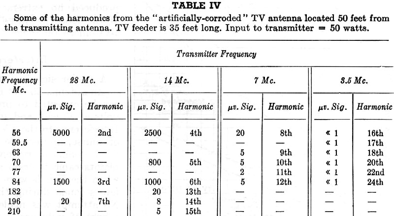
Table IV - Some of the harmonics from the" artificially-corroded" TV antenna located 50 feet from the transmitting antenna. TV feeder is 35 feet long. Input to transmitter = 50 watts. In the reverse direction, when W2CYZ was transmitting and the nonlinear system was 20 feet from the TV antenna at W2RYI, no visible interference was produced - but that was easy to fix! A 1N34 crystal clipped in series with an 8-foot wire loop across the TV feeder at W2RYI was all that was needed to generate enough harmonic output from Paul's harmonic-free signal to massacre Channel 2. Numerous other combinations of crystal and TV feeder were tried using the signal from 900 feet, and most of them produced objectionable interference. Two combinations that were particularly bad were set up to simulate conditions that could actually occur in standard TV installations. One represented a rusty lightning arrestor; the other, a corroded TV antenna. The "lightning-arrestor" joint consisted of a 1N34 diode clipped to one side of the 300-ohm line about 10 feet from the receiver. An 8-foot appendage from the diode was strapped to the water main where it emerged from the ground. The "corroded antenna" had an artificial joint that represented one of the many that can develop from weathering. The joint selected was located between the feeder terminal on the low-band folded dipole and the adjacent bolt from the steel support arm. A 1N34 diode clipped between these two points produced heavy Channel 2 interference in the tests with the signal from W2CYZ, and demonstrated the effectiveness of nonlinear joints that can develop on TV antennas.
Fig. 5 - Harmonic intensity as a function of the position of the third-harmonic appendage along a half-wave conductor. Frequency, 27 Mc.; power input, 320 watts; transmitting antenna 50 feet from harmonic-generating system; receiving antenna 20 feet from system.
Fig. 6 - Harmonic intensity as a function of the position of the second-harmonic appendage along a half-wave conductor. Same conditions as Fig. 5, except that appendage length is 102 inches. The artificially corroded TV antenna was also utilized to make measurements of the intensity of high-order harmonics produced by an efficient rectifier These measurements, shown in Table IV, indicate that the high-order harmonics are comparatively weak. Analysis of the data also indicated that the 35-foot TV feeder was not sufficiently long at 3.5 and 7 Mc. to develop optimum fundamental voltage on the rectifier. The optimum transfer of amateur fundamental signal to harmonics available at the receiver terminals occurs with a length of TV feeder that is resonant at the amateur fundamental, placing a voltage maximum at a rectification point common to both the feeder and a harmonic-resonant element in the TV antenna. Another optimum condition for nonlinear production of harmonics occurs when an amateur transmitting antenna has a rectifying joint. An "ideal" system would be available if a rectifier were substituted for the insulator at the end of a half-wave doublet, with a wire lanyard 1/2 wavelength for the second harmonic. Some day, someone is going to experience an exact duplicate of this condition - an old insulator with soot and rust and corroded copper wire - but almost any antenna or supporting structure is capable of developing a corroded joint at a point close enough to the optimum to produce potent harmonic signals. If an artificial joint 50 feet from a transmitting antenna can produce TVI at 900 feet, less efficient joints common to the antenna should certainly be suspected when TVI at close range is developed. Experiments with Joints as Mixers Getting back to the TV antenna, the diode connected to the support arm was utilized in examining the behavior of joints as mixers. Natural joints had been investigated with two signals transmitted simultaneously at W2RYI on several occasions, but data from controlled tests were needed for a better understanding of the results. At times, two separate transmitting antennas were used, but results were identical when the two signals were fed through a coax T-fitting to the discone transmission line, so the measurements made to produce the data for Figs. 7 and 8 were taken with a single source of radiation. One transmitter and a grid-dip oscillator had been used while tracking down the high-level sink joint. The signal from the grid-dip meter was fed into the BX, water, sewer, gas, and steam lines at various points along the lines while the regular transmitter was on 27 Mc. The water and sewer lines in the vicinity of the kitchen developed the strongest sum and difference signals, the grid-dip oscillator being run at 28.4 and 3.0 Mc. to develop signals at 1400 kc. for detection with the battery portable, and at 30 Mc. for checks in the communication receiver. Stronger and steadier mixed signals, of course, are developed when a second transmitter is run instead of the dipper, and, if work such as searching the neighborhood areas for joints is found necessary, a husky signal is advantageous. In any detecting operation, whether at broadcast frequencies or in the amateur or television bands, the receiver must reject the amateur fundamental. Traps or high-pass or low-pass filters may be required to prevent the production of harmonics or mixed signals in the receiving device.
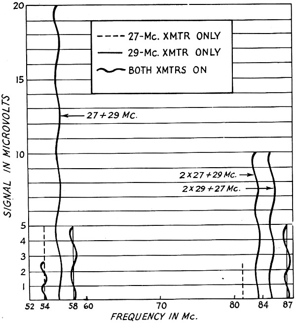
Fig. 7 - Harmonic and heterodyne signals from artificial joint on TV antenna. Two transmitters, each 50 watts input; transmitting antenna 50 feet from TV antenna. Two-signal transmissions produced some interesting data. Fig. 7 shows the major harmonic and sum-frequency signals between 50 and 100 Mc. that were developed in the TV antenna with the artificial joint. The power input to each transmitter was 50 watts; the transmitters were run individually at 27 and 29 Mc. and then simultaneously at the two frequencies. Readings taken for the individual transmitters showed that mixed signals developed between two and three times as much voltage as harmonics in the same frequency ranges. The harmonics had less amplitude when both transmitters were operating than when each transmitter was on by itself; the ratio of mixed-to-harmonic signal when both transmitters are operating runs between 5 and 30 to 1. No set pattern for the occurrence of various ratios is evident in the limited data represented by this graph, but the general observation holds that the mixed signals are stronger than the harmonics. The two-signal method can be utilized to advantage if the existence of detrimental nonlinear systems is questioned in a given location. If mixed signals are produced, the evidence helps confirm the presence of rectifying joints, and the general ratio of harmonic-to-mixed signal can be employed to approximate how much of the harmonic radiation is due to the transmitting equipment and how much is caused by the external systems. Another clue to the presence of rectifiers is available in locations where there is a strong local broadcast station. Mixed signals from the amateur and broadcast transmitters are sometimes available. With the artificially corroded antenna, modulated signals in the 10-to 20- microvolt range can be found 930 and 770 kilocycles from the 2nd and 3rd harmonics of 27 Mc. These signals are W2RYI mixture products of WPAT and WJZ, which are located, respectively, 5 and 10 miles away. On rare occasions, an audible arc may form at a corroded joint. Some of the "old timers," especially 'phone men, have had experience with talking bathtubs and hot-air ducts that called CQ. This type of modulated arc can produce r.f. harmonics as well as sound waves, but the sound may be easier to follow than the r.f. path when tracking down the source of the disturbance. There is one more example of sound indicating r.f. trouble: If the telephone picks up modulation from a transmitter, rectification is taking place, and r.f. harmonics are probably being produced. A New Phenomenon
Fig. 8 - Harmonic and heterodyne signals from natural joints at W2RYI. Two transmitters, each 300 watts input; signals picked up by TV antenna. An unusual phenomenon was immediately apparent when the readings were being taken on the mixed signals. Fig. 7 shows the effect as a differential between the radiation levels of a given harmonic when first one and then two fundamental signals are introduced to the diode. The 3rd harmonic of 27 Mc. was recorded as 1500 microvolts when the 27-Mc. transmitter was on the air alone. As soon as a 29-Mc. signal was added, however, the 81-Mc. signal dropped from 1500 microvolts down to 50. This was not a case of poor regulation! The power output of the 27-Mc. transmitter remained constant. It was a weird experience to raise the 29-Mc. power slowly from zero to maximum and watch the 81-Mc. signal drop inversely from maximum to minimum. Other harmonics shown on the graph behaved similarly, but the 3rd of 27 happened to be the most striking. The mechanism of this phenomenon may be cancellation by phase displacement or shift in the operating range of the crystal, or some other derangement that obeys the law of energy conservation. Whatever the cause, some day some application will come along that can utilize this screw-ball effect. In the meantime, it can be used as part of the evidence to convict kitchen sinks. Two Signals on Natural Joints Fig. 8 shows the normal two-signal radiation field at W2RYI. When this graph was made, the artificial joints had been tucked away in boxes on the shelf, and specific "bad" natural joints had been eliminated. The general trends in the graph pattern are similar to those in the artificial joint pattern of Fig. 7, adding to the evidence that the residual harmonic level is predominantly from external nonlinear systems. Occasionally, the natural joints at W2RYI produce signals at a lower level than that shown in Fig. 8, and at other times the intensity increases. Joints that produce heavy interference appear on an average of about once a year. As mentioned previously, some of the bad joints are difficult to eliminate, so shunting them with a conductor is an alternative. The accessibility of the junction determines the length of the shunt that can be employed, but shunts that are long have too much inductance.
Fig. 9 - Effect of length of shunt across optimum second-harmonic nonlinear joint. Shunt lengths are evaluated in Fig. 9. The data plotted represent the radiation characteristics of the optimum 2nd-harmonic system with various lengths of No. 14 copper wire connected across the diode. The actual shunt path includes the distance along the conductors on both sides of the crystal. If attenuation of more than 10 to 1 is desired, it is apparent that a total shorting path of less than 15 inches is necessary. Readings were also taken with an optimum 3rd-harmonic system. The curves for the 2nd and 3rd harmonics were identical in shape, but were 6 db. apart. No obvious resonances were found during the shorting tests. The shunt evidently does a straight-forward job of reducing the fundamental r.f. voltage across the crystal. There may be some resonance tricks that can be performed on the lines common to an inaccessible joint, but the. possibilities seem remote. There are, however, other tricks to try that are based on known procedures. For instance, a beam antenna could be so situated that the heading toward the house would be the one most seldom used. Improvement in the order of 10 to 20 db. could be derived. If the shack is on a farm, putting the antenna far away - and high - will reduce the fundamental field. Sometimes changing the polarization from horizontal to vertical, or vice versa, will reduce the strength of the signal reaching a specific, troublesome conductor. Perhaps a ground-plane antenna placed on top of the house would reduce the r.f. field below sufficiently to eliminate TVI from inaccessible joints; this is an opportunity for the antenna boys to come up with data on a super signal squirter with a high "front-to-bottom" ratio. There are probably other tricks that expediency will bring forth. Building a new house with all components designed to obviate metallic contacts might be the ultimate, but that would be the last resort! The number of amateurs that would go to such an extreme is limited. As a matter of fact, the number that will experience nonlinear system difficulties may be very small. It is difficult to predict, from the meager statistics available, what the trend will be. A few stations have had one or more proven cases. A favorable number have apparently had no difficulties. A group of unknown size having partially TVI-proofed transmitters mayor may not know that they are having nonlinear system difficulties. And a happy-go-lucky gang, the boys who start activities after the last local television station lowers its flag for the night and plays the "Star-Spangled Banner," may never know! * c/o Tube Dept., RCA Victor Div., RCA, Harrison, N.J.
Posted November 24, 2022 |
|