A Self-Contained Handie-Talkie |
|
"Handie-Talkie" was the name given to early walkie-talkies used in the field by military communications troops. Having been written during World War II, the author of this QST article just assumed that any reader would be familiar with the WERS acronym - it stands for War Emergency Radio Service. Per the Wikipedia entry: "At the start of the Second World War the United States Congress had suspended all amateur radio activity throughout the country. WERS was established by the Federal Communications Commission in June 1942 at the insistence of the American Radio Relay League. WERS would remain in operation in through the end of the Second World War in 1945. WERS was to provide communications in connection with air raid protection, and communications during times of natural disaster. WERS licenses were given to communities and not individuals. One of the requirements for individuals to participate in the WERS was to hold an Amateur radio license." See also The Walkie-Talkie - March 1955 Popular Electronics, A Self-Contained Handie-Talkie - June 1944 QST, and The New Handy-Talkie - December 1942 Radio-Craft, Walkie-Talkies: Something for Everyone - April 1974 Popular Electronics, A Self-Contained Handie-Talkie - June 1944 QST, Inside the Handie-Talkie - July 1946 Radio-Craft. A Self-Contained Handie-Talkie A Compact Light-Weight WERS Unit Operating from Dry Batteries By Charles T. Haist. Jr., W6TWL. EX-W9EQL
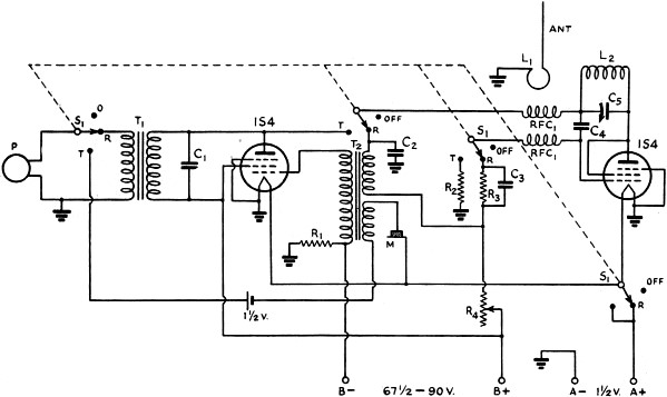
When necessary, however, surprising distances can be covered with handie-talkie units when they are operated in the clear. Communications with control center KMFY-1, with a signal report of R4/S4 at distances up to ten miles, have been accomplished with the hand-portable shown in the photographs. R5/S5 reports have been logged at distances of up to three or four miles. This unit is built along the lines of some of those used by the armed forces. The complete transceiver and its battery power supply, enclosed in an aluminum case as shown, weighs but 3 7/8 pounds. The outside dimensions of the case are only 2 5/8 X 2 3/4 X 11 inches. Circuit Details The transceiver circuit, shown in Fig. 1, is more or less conventional in most respects. It was drawn up around the type 1S4 tube, which is the secret of the set's compactness. Two tubes of this type are used in the unit. One, with its screen tied to the plate, is used as a triode oscillator and detector. The other 1S4 is used as an audio amplifier and modulator. Many have encountered trouble in getting the 1S4 to super-regenerate on frequencies as high as 112 Mc. In this circuit this difficulty was solved by placing a 0.005-μfd. condenser, C3, across the receiving grid leak, R3. * 750 Warfield Ave., Oakland 10, Calif. The microphone is insulated from the aluminum case so that it may be connected in series with the single headphone, P, for side-tone transmitting. The headphone, which has an impedance of about 100 ohms, was provided with an output transformer, T1, for proper impedance matching to the output of the 1S4. When transmitting, the secondary is opened and the primary is used as a Heising modulation choke.
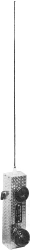
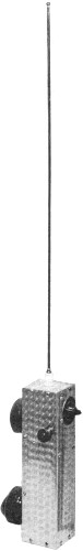
The change-over switch, S1, is a four-pole triple-throw rotary switch. In addition to the two usual positions, a third position, labeled 0 in Fig. 1, is provided where all battery circuits are open. The filament circuit is completed when the switch is placed in either the receiving or the transmitting position. The filament battery consists of two No. 3 flashlight cells connected in parallel for longer life. They are held in the case by spring clips. The plate battery is a 67 1/2-volt Minimax or two 45-volt hearing-aid batteries in series. These batteries are not too difficult to buy now, since stores are selling them on the open market after the nominal installation date has passed. One penlite cell provides adequate voltage for the microphone. Construction The case for the unit is made of pieces of sheet aluminum fastened together with self-tapping screws. The metal was given a "swirl" finish by applying a spinning cork, held in the chuck of a drill press, after the aluminum sheet had been smeared with a thin coating of a mixture of valve-grinding compound and oil. The microphone, mounted in the lower end of the panel, and the single headphone at the top are from a Western Electric handset in which the brass threads moulded in the handle were cut off with a hacksaw to provide mountings. The regeneration control is on the right side and the change-over switch on the left side in a position convenient for one-hand operation. These two views of W6TWL's hand-portable transceiver show the arrangement of controls. The left-side view shows the headphone. microphone, and, on the side. the change-over switch. The right-side view shows the regeneration control on the side and the tuning knob and scale on the rear. The batteries occupy the lower section of the case, the "A" battery cells being mounted in clips at the bottom and the "B" battery immediately above. The penlite microphone battery is mounted in a clip on top of the headphone transformer. The transceiver components consume the remaining space at the top. The r.f. tube is mounted in an inverted position in a polystyrene socket, while the audio tube socket is fastened to a shelf at the left in the inside view of the unit. The tank coil, L2, is soldered directly to the terminals of the tuning condenser, C5, which is mounted immediately below the antenna terminal. The antenna is a quarter-wave rod, 24 inches long, which plugs into a receptacle on top of the case. It is coupled to the tank coil by a single turn of wire, L1, one end of which is grounded to the case. With this arrangement transmission and reception seem to be good even with the antenna at an angle or in a horizontal position. This transceiver has seen considerable successful service during the past few months. The life of the batteries is very good despite their small size, since the current drain on the filament battery is only 200 ma. and the total "B" battery current is only 10 ma. when receiving and 15 ma. when transmitting. The handie-talkie unit with the front cover removed. The miniature plate and filament batteries occupy the lower portion of the case, while the r.f. and audio components are fitted into the top section.
A Self-Contained Handie-Talkie Schematic Diagram Fig. 1 - Circuit diagram of W6TWL's hand-portable WERS station. C1 - 0.001-μfd. midget mica. C2 - 0.003-μfd. midget mica. C3 - 0.005-μfd. midget mica. C4 - 50-μfd. midget mica. C5 - 2-plate midget variable. R1 - 750 ohms, 1/2-watt carbon. R2 - 25,000 ohms, 1/2-watt carbon. R3 - 10 megohms, 1/2-watt carbon. R4 - 100,000-ohm potentiometer (regeneration control). L1 - 1 turn No. 12, 1/2-inch inside diameter. L2 - 4 turns No. 12, 1/2-inch inside diameter. RFC1 - V.h.f. r.f. choke (Ohmite Z-0 or homemade equivalent). M - Single-button carbon microphone (see text). P - Single headphone, 100 ohms (see text). S1 - Four-pole three-position rotary switch. T1 -8000- to 100-ohm output transformer. T2 - Transceiver transformer.
Posted October 19, 2020 |
|
 The application of units of the handie-talkie type to WERS work is very
practical in that they may be operated right at the scenes of incidents or disaster,
leaving the operator free to walk or move around and still have one hand available
to assist in other duties. Such low-power units are intended primarily to be used
in conjunction with a higher-powered mobile unit which may be located several blocks
away, parked in a favorable spot which permits satisfactory communication with the
control center for the purpose of relaying messages.
The application of units of the handie-talkie type to WERS work is very
practical in that they may be operated right at the scenes of incidents or disaster,
leaving the operator free to walk or move around and still have one hand available
to assist in other duties. Such low-power units are intended primarily to be used
in conjunction with a higher-powered mobile unit which may be located several blocks
away, parked in a favorable spot which permits satisfactory communication with the
control center for the purpose of relaying messages.