| January 1944 Popular Mechanics |
 [Table of Contents] [Table of Contents]
Wax nostalgic about and learn from the history of early
mechanics and electronics. See articles from
Popular Mechanics,
published continuously since 1902. All copyrights hereby acknowledged.
|
I love a finely crafted
gear as much as I do a fancy vacuum tube. Worm gears are my favorite, maybe because
they are what I call the "diode" of gears. Due to their construction, applying
a torque force to the cylindrical worm gear transfers its rotation to the circular
mating gear (worm wheel); however, applying the torque to the worm wheel
will not impart a torque backward to the cylindrical worm gear. It's one-way action
accommodates a force transfer in just one direction, like a diode. There is no need
for a lock or ratchet to prevent the output from affecting the input. That is why tuning pegs on stringed instruments use
worm gears. It is why the drive gears on telescope axes use worm gears. Winches
use worm gears. One of the downsides of worm gears is that there is no rolling force
between surfaces - only a sliding force - so good lubrication is essential to prevent
excessive wear. This "ABC of Gears and Gear Cutting" story from a 1944 issue of
Popular Mechanics magazine is a fairly in-depth dive into gear theory and
manufacturing - and not just for worm gears. Another of my favorite gear types
is the Geneva gear,
used by clocks and movie projectors.
The ABC of Gears and Gear Cutting
 By H. J. Chamberland By H. J. Chamberland
Gears play a highly important role in many products where it is necessary to
transmit power from one part to another within a limited space, especially in the
case of machine tools. With this in view, any machine-shop worker should know something
about gears and the nomenclature involved, inasmuch as he may be put to working
in connection with their production, and certainly will have occasion at some time
or other to make use of them. However, in this article, which covers the subject
of gears only in an elementary way, most information relating to gear design will
be omitted.
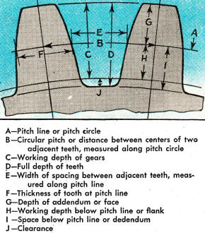
Gear terminology.
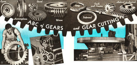
Common Types of Gears
Depending upon requirements, gears are made in various types and sizes. Their
success or failure, and also their length of service, depend to a great extent on
the material from which they are made and the heat treatment given, while their
efficiency of operation is governed largely by the accuracy of the tooth form. Spur
gears, shown in the heading and also in Figs. 1, 3 and 12, are the most common in
use. Their teeth are cut straight across, parallel to the axis of the blank disk
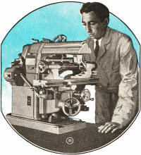
from which they are machined. The diameter of the bore of a gear must be checked
with considerable accuracy, for which purpose vernier calipers are used as shown
in Fig. 1. Other types of gears are known as helical (or spiral), herringbone, bevel
and miter (a 45° bevel gear) and worm gears, which are shown in the heading.
The smaller gear of a pair is called a pinion; a gear at the source of power is
referred to as a driving gear or a driver, while one to which power is transmitted
from the driver is called a driven or follower gear. A "train" of gears consists
of several arranged in any combination, as for instance a train of gears found in
a screw-cutting lathe as in Fig. 2.
Gears Versus Frictional Wheels
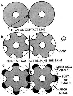
If two disks or wheels are held so that their circumferences contact each other
as shown in detail A of Fig. 4, a rotation of one will cause the other to rotate,
provided the friction between the two is sufficient. Obviously, some power can be
transmitted in this way but where it is necessary to transmit considerable power,
friction alone between the surfaces is undependable, as there may be slippage. This
inefficiency is basically the reason for having gears, which are simply disks or
wheels to which teeth are added so that intermeshing gears can rotate without slippage,
power being transmitted by the teeth. You will note from details B and C of Fig.
4 just how gears having the same diameter as the disks in detail A, are evolved.
A number of equal-size, semicircular portions are cut out equidistantly on the circumference
of the disks, after which the cut-out pieces are joined to the disks on the intervening
spaces or "lands" along the circumference, to form teeth. Note that in the transformation
from disks to gears, the center-to-center distance has remained the same, but that
the outside diameter of the gears is greater than the diameter of the disks.
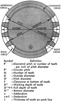
 Pitch Circle and Pitch Diameter Pitch Circle and Pitch Diameter
When referring to the size of gears, as in machine-design drawings, it is not
the outside diameter which is meant, nor the inside or "root" diameter along the
bottom of the teeth, but the diameter at the approximate center of the teeth-in
other words, the diameter of the disks in detail A of Fig. 4. This is known specifically
as the "pitch diameter," while the circumference of the disk becomes the "pitch
circle" of the gear. Fig. 6 shows the three diameters of a gear and the relating
circles, while Fig. 7 gives gear symbols.
Diametral Pitch
With the meaning of pitch diameter and pitch circle established, it is easy to
understand what is meant by "diametral pitch," a term designating the tooth size
of a gear. It is not an actual dimension but it is the ratio between the number
of teeth on the gear and its pitch diameter in inches. Thus, a 4 diametral pitch
gear has four times as many teeth as it has inches of pitch diameter. If the latter
were 12 in., there would be 48 teeth on the gear. In other words diametral pitch
is the number of teeth per inch of pitch diameter. Spacing and size of the teeth
can be determined readily from this information.
Circular Pitch
On large gears, the tooth size may be designated by the term "circular pitch."
This is the distance between the centers of two adjacent teeth measured on the pitch
circle as indicated by B in Fig. 5. To translate this into equivalent diametral
pitch, you divide 3.1416 by the circular pitch. Or, if you desire to know the circular
pitch when only the diametral pitch is given, you simply divide 3.1416 by the diametral
pitch. For examples, refer to Fig. 10. The number of teeth on the circumference
of a gear is largely determined by the amount of power that must be transmitted
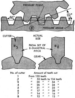
from one gear to another, and the strength of the gear teeth themselves. The angle
at which the gear teeth press against teeth of a mating gear or rack is called the
pressure angle as indicated in Fig. 8. In gear-cutting practice, pressure angles
of 14 1/2 and 20 degrees are commonly used. For calculating the size of gears, there
are eight important formulas and examples listed in Fig. 10 . These can be
applied without much knowledge of mathematics. However, to go deeper into gearing
such as computing helical, bevel, worm gears, as well as the more complicated types,
one must expect to deal in geometrical terms.
 Gear-Cutting Sets Gear-Cutting Sets
If the teeth of all gears had to be cut with separate cutters, a considerable
and prohibitive investment for cutters would be required. Hence, for the sake of
economy and simplification, a system is in practice whereby sets of cutters, each
comprising eight cutters for each pitch, will handle all problems. Fig. 9 shows
the comparative increase in radius between a No.5 and a No.8 cutter of the 8-diametral
pitch set. The tooth form of a cutter of a set remains fixed and this cutter will
produce the precisely correct tooth form only on a gear of certain diameter and
number of teeth.
Each cutter of a set is designed to be perfectly correct for the lowest number
of teeth in the range it covers. For example, a No.2 cutter, which cuts from 55
to 134 teeth, has the correct curve for 55 teeth, so the more teeth this cutter
has to cut the more rounded will be the teeth of the gear because the length of
the bearing on each tooth decreases as the number of teeth increases. Naturally,
gears cut according to this procedure cannot be expected to operate as smoothly
as they would when having their individual or theoretical curve.
Gear-Cutting Procedures
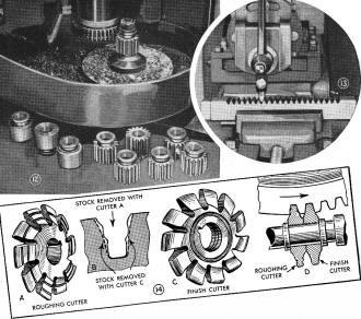
Gear teeth are cut by milling, hobbing and shaping. Hobbing, a specialized form
of milling and gear shaping, is done in a machine having no connection to a conventional
shaper. The operation is similar to a milling operation and small gear cutters are
often cut in gangs as shown in Fig. 11 by completing each flute with a single cut.
Larger gears usually are made by cutting them singly using a roughing or stocking
cutter first; detail A of Fig. 14, and then a regular finish cutter as shown in
detail C. The effect of the roughing cutter is shown in detail B.
 The grooved teeth of this cutter have a
chip-breaking action, which permits faster and cleaner cutting with very little
stock remaining for finishing. When cutting gears of large size, both cutters may
be operated in a gang as shown in detail D, in which case the cutters do their work
simultaneously and at a marked saving in time. The grooved teeth of this cutter have a
chip-breaking action, which permits faster and cleaner cutting with very little
stock remaining for finishing. When cutting gears of large size, both cutters may
be operated in a gang as shown in detail D, in which case the cutters do their work
simultaneously and at a marked saving in time.
 The hobbing method of gear cutting shown
in Fig. 16 is continuous rather than intermittent as with a plain cutter, which
requires indexing for each tooth. The cutting tool is a hob, which resembles a worm
gear except that it has cutting teeth and produces equally spaced teeth on a cylindrical
surface. The hob and the gear blank revolve at correct relative speeds by means
of gearing, the hob advancing uniformly to cut teeth with the correct pitch. The hobbing method of gear cutting shown
in Fig. 16 is continuous rather than intermittent as with a plain cutter, which
requires indexing for each tooth. The cutting tool is a hob, which resembles a worm
gear except that it has cutting teeth and produces equally spaced teeth on a cylindrical
surface. The hob and the gear blank revolve at correct relative speeds by means
of gearing, the hob advancing uniformly to cut teeth with the correct pitch.
The most productive method of gear cutting is by shaping, as in Fig. 12. A gear
shaper uses a cutting tool which is essentially a hardened gear with its teeth properly
relieved. When starting to cut a gear, the cutter is first fed down against the
edge of the blank to proper depth, after which it reciprocates at a speed of about
800 strokes per minute while both gear blank and cutter revolve and the teeth on
the blank are cut in one rotation of the Blank. However, often two cuts are taken
for extremely precise tooth forms. This method is efficient, as one cutter of any
pitch will cut any number of teeth of that pitch, whereas a formed cutter will cut
but a limited number of teeth.
As shown in Fig. 13, teeth in gear racks are often produced in regular shapers
and even planers with a tool bit formed accordingly. This procedure is rather slow,
as each tooth must be cut separately, but the procedure is practical to duplicate
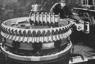
a broken or worn part. In quantities, racks are cut as shown in Fig. 15. The herringbone
gear being cut by the shaping method in Fig. 17 actually comprises two helical gears
with teeth angles in opposite directions. Such a gear is often made in two parts
with a milling cutter or end mill, but can be cut also by shaping. Helical (or spiral)
and herringbone gears are used extensively to transmit heavy loads with extreme
quietness, as for example in autos. Except for somewhat more involved computation
of tooth form, these gears can be machined as easily as spur gears.
 A bevel gear, has its teeth cut on an angular
face to transmit power to shafts set at an angle to each other. When both shafts
are at an angle of 45 degrees, the gears are known as miter gears. In this the teeth
are usually straight but they also can be cut spirally for increased strength and
driving power plus smooth operation. The cutting of bevel gears involves a different
problem than other types due to the difference in diameter at both ends of the gear
blank. The diametral pitch of bevel gears is that of the larger end of the teeth
but the pitch gradually changes toward the smaller end. Due to this change in pitch,
bevel gears can be cut accurately only by shaping if quantity is involved. However,
for quality, the teeth can be milled to their greatest extent and the small ends
finished by filing them to produce their shape as nearly correct as possible. This
latter course requires extreme care since the maximum bearing point of those gears
should be at the small end. A bevel gear, has its teeth cut on an angular
face to transmit power to shafts set at an angle to each other. When both shafts
are at an angle of 45 degrees, the gears are known as miter gears. In this the teeth
are usually straight but they also can be cut spirally for increased strength and
driving power plus smooth operation. The cutting of bevel gears involves a different
problem than other types due to the difference in diameter at both ends of the gear
blank. The diametral pitch of bevel gears is that of the larger end of the teeth
but the pitch gradually changes toward the smaller end. Due to this change in pitch,
bevel gears can be cut accurately only by shaping if quantity is involved. However,
for quality, the teeth can be milled to their greatest extent and the small ends
finished by filing them to produce their shape as nearly correct as possible. This
latter course requires extreme care since the maximum bearing point of those gears
should be at the small end.
Worm gearing is also somewhat different than other forms of gearing. As shown
in Fig. 16, it consists of a screw and worm wheel, the latter being somewhat similar
to a helical gear with its face concaved to match the form of the screw thread.
When a hobbing machine is not available, worm wheels may be cut by milling. In this
case the procedure is to set the milling machine table at the proper angle, after
which the operator proceeds to rough the teeth with a cutter of predetermined diameter
by repeatedly indexing and feeding the wheel against the cutter vertically. Then
the correct tooth form is produced as in Fig, 18, with a hob fitted to an arbor
and the assembly revolving freely between centers with the teeth of the hob meshing
with the rough teeth of the wheel. In this case however a machine of the vertical
boring mill type was used. Fig. 16 is a regular hobbing machine setup and the depth
of tooth is shown being checked with a gear-tooth vernier. The worm wheel also shown
in Fig. 18 presents no form cutting difficulties. The screw form can be produced
in this or in another type of milling machine with a hob or plain-formed cutter,
in a hobbing machine, in a specially tooled gear shaper or in a lathe.
 (10) - How Gears Are Sized (10) - How Gears Are Sized
To Find Diametral Pitch (P) when number of teeth and outside diameter are known.
Add 2 to number of teeth and divide by outside diameter. Example: 40 teeth and 10
1/2 in. diameter: 40 plus 2 divided by 10 1/2 in. equals 4. Ans. 4 diametral pitch.
To Find Circular Pitch (P') when diametral pitch is known. Divide 3.1416 by diametral
pitch. Example: 4 diametral pitch: 3.1416 divided by 4 equals 0.7854 in. Ans. 0.7854
cir. pitch.
To Find Number of Teeth (N) when outside diameter and diametral pitch are known.
Multiply outside diameter by diametral pitch and subtract 2. Example: 10 1/2 diameter
and 4 diametral pitch: 10 1/2 in. multiplied by 4 and minus 2 equals 40. Ans. 40
teeth.
To Find Outside Diameter (D) when number of teeth and diametral pitch are known.
Add 2 to number of teeth and divide by diametral pitch. Example: 40 teeth and 4
diametral pitch: 40 plus 2 divided by 4 equals 10 1/2. Ans. 10 1/2 in. outside dia.
To Find Pitch Diameter (D') when number of teeth and diametral pitch are known.
Divide number of teeth by diametral pitch. Example: 40 teeth and 4 diametral pitch:
40 divided by 4 equals 10. Ans. 10 in. pitch dia.
To Find Clearance (f)
when diametral pitch is known. Divide 1.57 by diametral pitch. Example: 4 diametral
pitch: 1.57 divided by 4 equals 0.392 in. Ans. 0.392 clearance.
To Find Full Depth of Tooth (working depth plus clearance) when diametral pitch
is known. Divide 2.157 by diametral pitch. Example: 6 diametral pitch: 2.157 divided
by 6 equals 0.3595 in. Ans. 0.3595 full depth of tooth,
To Find Thickness of Tooth at Pitch Line (t)
when circular pitch is known. Divide circular pitch by 2. Example: 1.047 circular
pitch: 1.047 divided by 2 equals 0.523 in. Ans. 0.523 thickness of tooth.
Posted November 22, 2023
|